E-flite PT-19 450 ARF User Manual
Page 21
21
E-flite PT-19 ARF Assembly Manual
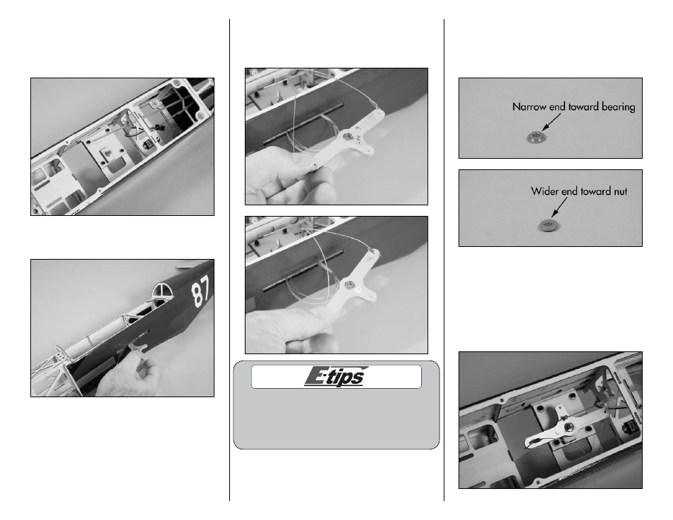
5. Use four 4-40 x 1/2-inch socket head screws
and four #4 washers to secure the bellcrank base
inside the fuselage. Note that the threaded stud for
the bellcrank is facing the slot in the fuselage for
the leadout wires.
6. Slide the elevator bellcrank into the fuselage
through the slot exposed in Step 1.
7. Insert the brass pushrod connector into the
hole in the elevator bellcrank. Use pliers and the
connector backplate to secure the brass pushrod
connector to the elevator bellcrank.
You will note in the pictures we have installed
the pushrod connector in the inner hole on the
bellcrank. This will provide good solid control inputs
for your first flights. Later on, you may move to the
outside hole for even more throw if you so wish.
8. Carefully inspect the flanged washer. Is must be
installed in the correct direction for the bellcrank to
operate smoothly. The narrow part of the flange will
fit against the bearing in the bellcrank, and the wide
edge faces the nut holding the assembly together.
9. Slide the bellcrank onto the threaded stud. Make
sure the mark made in Step 3 is facing up. Slide
the flanged washer onto the threaded stud (not the
correct direction as described in the previous step)
and use the nut and 5.5mm nut driver to tighten the
nut. Snug the nut down to prevent damage to the
bearing in the bellcrank. Insert the elevator pushrod
into the hole in the brass pushrod connector.