Cowling and propeller installation, rc/cl options – E-flite PT-19 450 ARF User Manual
Page 27
27
E-flite PT-19 ARF Assembly Manual
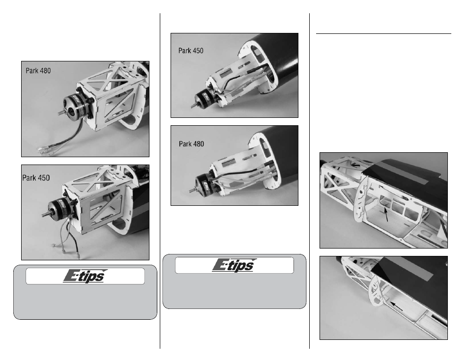
2. Attach your motor to the firewall using four
4-40 x 1/2-inch socket head screws and four
#4 washers. Tighten the screws using a 3/32-
inch ball driver or hex wrench. Make sure to use
threadlock on the four screws to prevent them from
vibrating loose.
The blind nuts in the fuselage for mounting the motor
can be positioned for a variety of motors. Position the
blind nuts so they are aligned with your particular
motor before mounting the motor to the firewall.
3. Connect the leads from the motor and speed
control at this time.
4. Check the operation of the motor at this time.
It should rotate counterclockwise when viewed
from the front of the aircraft. If not, follow the
instructions provided with your speed control to
correct the situation.
Never check the motor rotation on the bench
with the propeller installed. The plane could
move and cause serious injury. Always check the
motor without the propeller to avoid injury.
Cowling and Propeller Installation,
RC/CL Options
Required Parts
Fuselage assembly Cowling
Propeller adapter Propeller
2mm x 8mm sheet metal screw(4)
Required Tools and Adhesives
Card stock
Low-tack tape
Scissors
Pin drill
Thin CA
Phillips screwdriver: #1
Drill bit: 1/16-inch (1.5mm), 1/8-inch (3mm)
1. Locate the cowl mounting plates inside the
fuselage. There are two on each side. These plates
reinforce the fuselage where the cowl mounting
screws will be positioned.