Installation instructions – Brandmotion 1013-9531-V2 User Manual
Page 9
INSTALLATION INSTRUCTIONS
9530 & 9531 Instructions 1-14-13.doc
Page 9 of 16
Figure 36
D. Insert the pink wire from Connector C12/ X12
into the other cavity in the Denali Jumper
Harness. (Figure 37)
Figure 37
E. Slide gray TPA over to lock wires into place.
F. Snap the supplied Denali Jumper Harness into
other half of Denali Jumper on supplied Mirror
Harness. (Figure 38). Then, connect pink wire of
Denali Jumper Harness to cavity 7 of C12/ X12
connector (where pink wire was removed).
Figure 38
47. Re-insert TPA and plug C12/ X12 Connector into M-
BEC. (Figure 26) Proceed to Step 49.
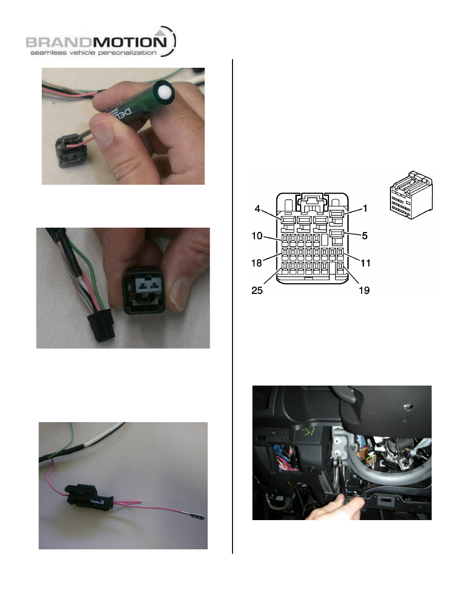
48. If all M-BEC connections are secure and no
fuses are blown and reverse still is not
present, reverse must be located in the under dash
BCM left of the steering wheel. (Figures 25 & 39)
A. Cut the connector off the green Reverse (+) wire
of supplied Mirror Harness and splice to wire in
brown BCM X5 Connector Cavity 7. (Figures 25 &
39)
Figure 39
B. Cut the terminal off the pink ignition (+) wire of
supplied Mirror Harness and splice to wire in brown
BCM X5 Connector Cavity 13. (Figures 25 & 27)
49. Locate Ground Ring Terminal on black wire of
supplied Mirror Harness and attach at the lower
knee bolster stud using supplied Ground Nut and a
10mm socket. Tighten to 4 N·m (36 lb in). (Figure
40)
Figure 40