Rockwell Automation 2198-Hxxx Kinetix 5500 Drive Systems Design Guide User Manual
Page 10
10
Rockwell Automation Publication GMC-RM009D-EN-P - June 2014
Kinetix 5500 Drive Systems
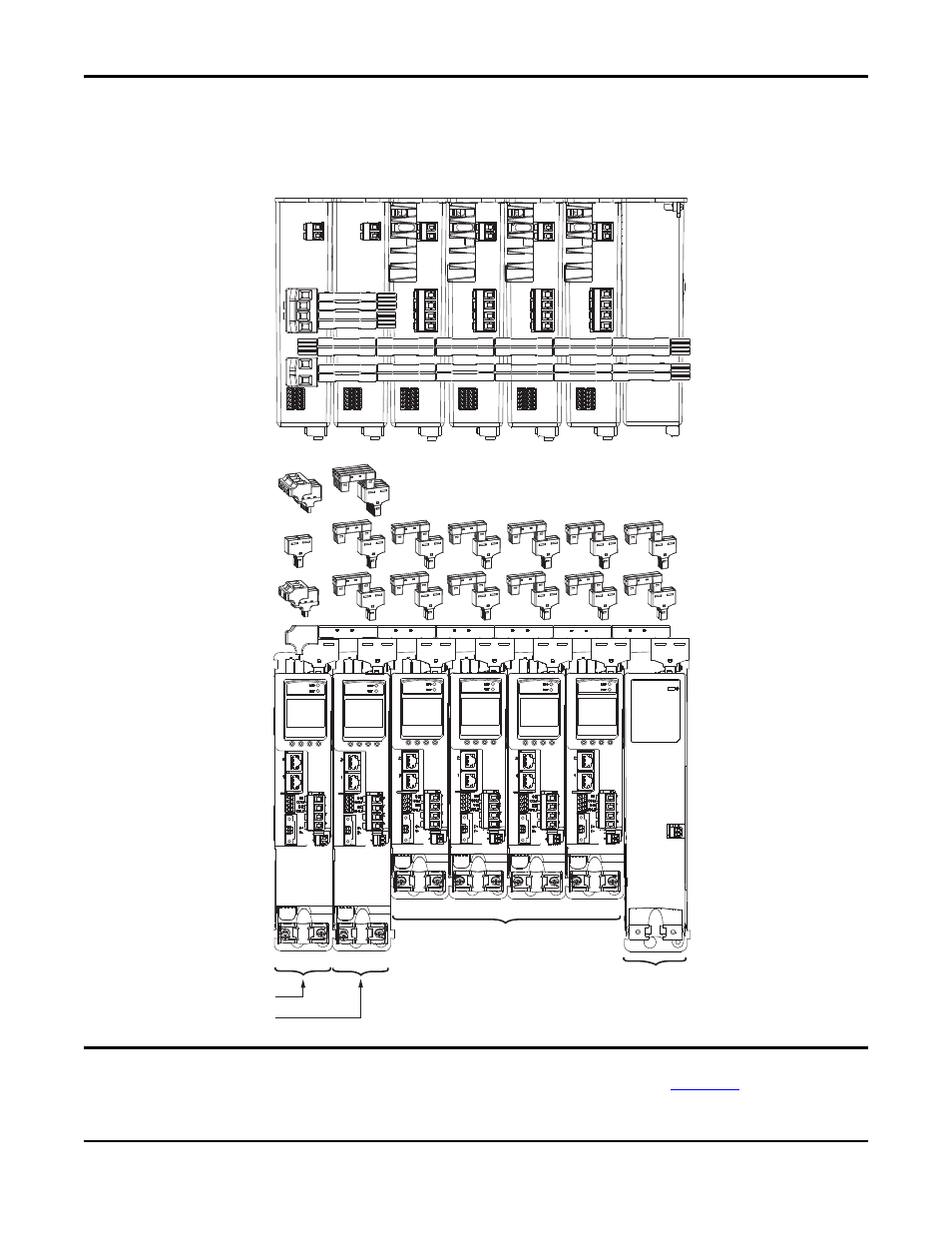
In this example, three-phase AC input power is supplied to two converter drives with the same power rating. This parallel
converter configuration increases the DC power supplied to the inverter drives.
Shared AC/DC Bus Hybrid Installation Example
IMPORTANT
In shared AC/DC hybrid configurations, the two converter drives must have the same power rating and must be greater than or
equal to the inverter drives. Refer to the Kinetix 5500 Servo Drives User Manual, publication
, for system sizing
information, including restrictions on how many drives can be connected in the shared AC/DC, shared DC (common bus), and
hybrid configurations.
+
+
+
+
+
+
2198-H040-ERS
x
Common-bus (converter)
(frame 2) Leader Drives
2198-H008-ERS
x
Common-bus (inverter)
(frame 1) Follower Drives
2198-CAPMOD-1300 Capacitor Module
(optional component) Front View
2198-CAPMOD-1300 Capacitor Module
(optional component) Top View
2198-H
xxx-ERS
Kinetix 5500 Servo Drives are Shown
(top view)
Three-phase
Input Power
Shared AC (mains AC input)
Shared 24V (control power input)
Shared-bus Connection System
(front view)
AC Input
Connector
Control Power
Input Connector
Bus-bar Connectors and
AC Bus T-connectors
Bus-bar Connectors and
Control Power T-connectors
24V Control Input Power
Axis 1
Axis 2
Axis 3
Axis 4
Axis 5
2198-H040-ADP-IN
DC Bus
Shared DC Bus
DC Bus
Connector
Bus-bar Connectors and
DC Bus T-connectors
2198-H
xxx-ERS
Kinetix 5500 Servo Drives are Shown
(front view)
Axis 6
2198-H040-ADP-T
2198-H040-DP-T
2198-KITCON-CAP1300
(ships with capacitor module)