Rockwell Automation MinPak Plus DC Drive User Manual User Manual
Page 42
5:11
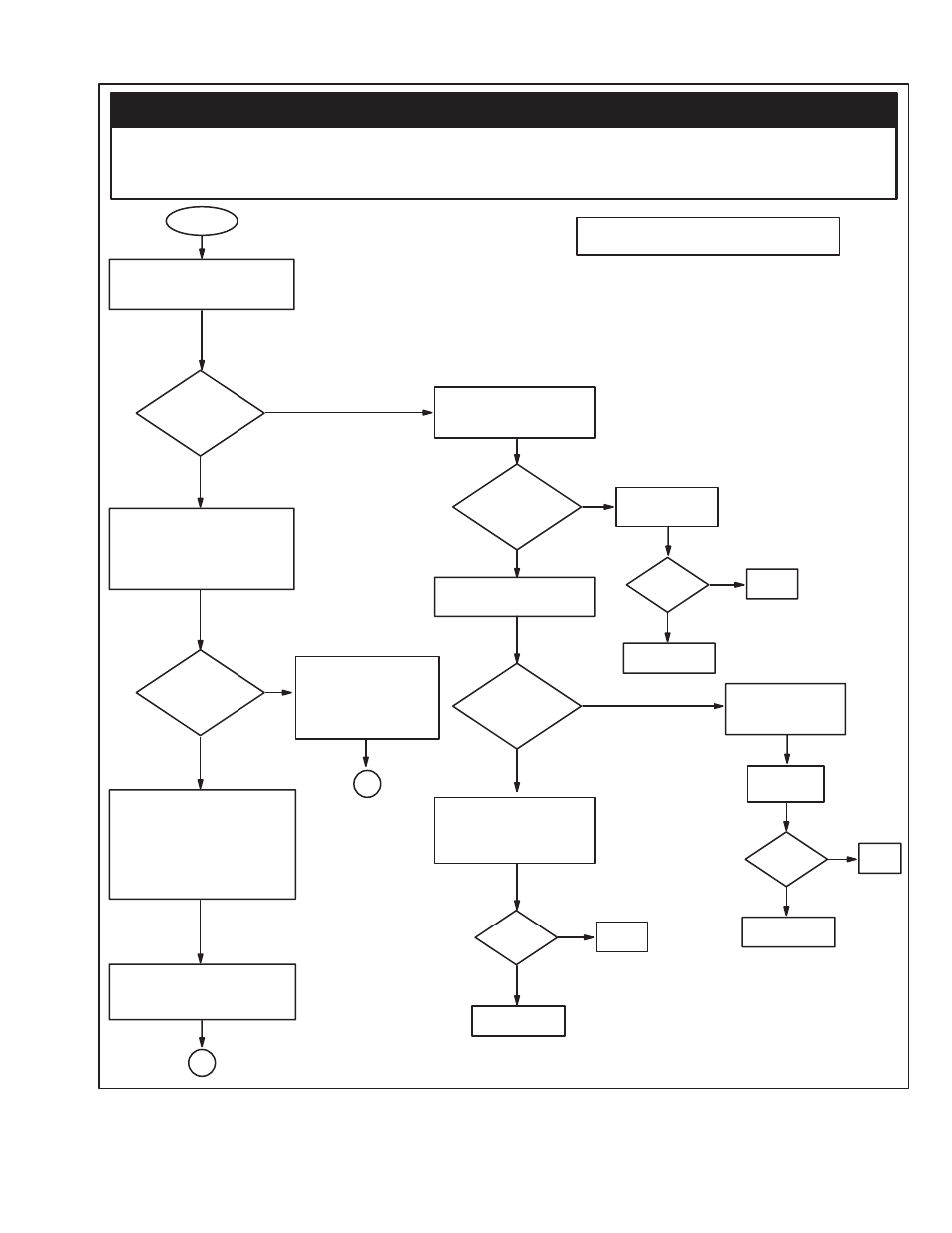
Check for speed reference 0 to
8 VDC between terminals 126
and 57 (common).
Is
reference
voltage
present?
Check power supply voltages:
+11.2 VDC between terminals
56 and 57 (common)
-11.2 VDC between terminals
71 and 57 (Common)
Are
power supply
voltages
present?
At this point, if an Instrument
Interface Kit, Voltage Tach FolĆ
lower Kit, or a Dancer Follower
Kit is being used, go to Drive
Using Reference Kit" TroubleĆ
shooting Flowchart, if not,
continue.
Check reference voltage beĆ
tween terminals 426 and 57
(Common).
Start
Done
A
Check DĆC Bus voltage 0
to 90, or 180 VDC between
terminals 47 and 45.
Is DĆC Bus
voltage
present?
Check armature voltage
at terminals A1 and A2.
Replace
regulator board
B
Is armature
voltage
present?
Fixed?
See Note #1
Loose/open wiring or bad
FM Contactor power conĆ
tact between 47 and 45 to
A1 and A2.
Yes
No
Yes
No
Yes
No
Done
Fixed?
See Note #1
Yes
No
Possible motor or
motor wiring probĆ
lems.
Done
Fixed?
See Note #1
Yes
No
Correct the
problem
Check for 18 VAC beĆ
tween PINS 281 and
57, and PINS 282 and
57 of the regulator
board.
Note #1: Contact local sales/service office.
Yes
No
Yes
No
Go to
next page
Go to
next page
DANGER
SOME OF THE FOLLOWING CHECKS AND PROCEDURES REQUIRE THE POWER TO BE ON. EXERCISE
EXTREME CARE AS HAZARDOUS VOLTAGE EXISTS. FAILURE TO OBSERVE THIS PRECAUTION COULD
RESULT IN SEVERE BODILYINJURYOR LOSS OF LIFE.
Figure 5Ć8. M" Contactor PicksĆUp But Motor Does Not Run.