Rockwell Automation MinPak Plus DC Drive User Manual User Manual
Page 40
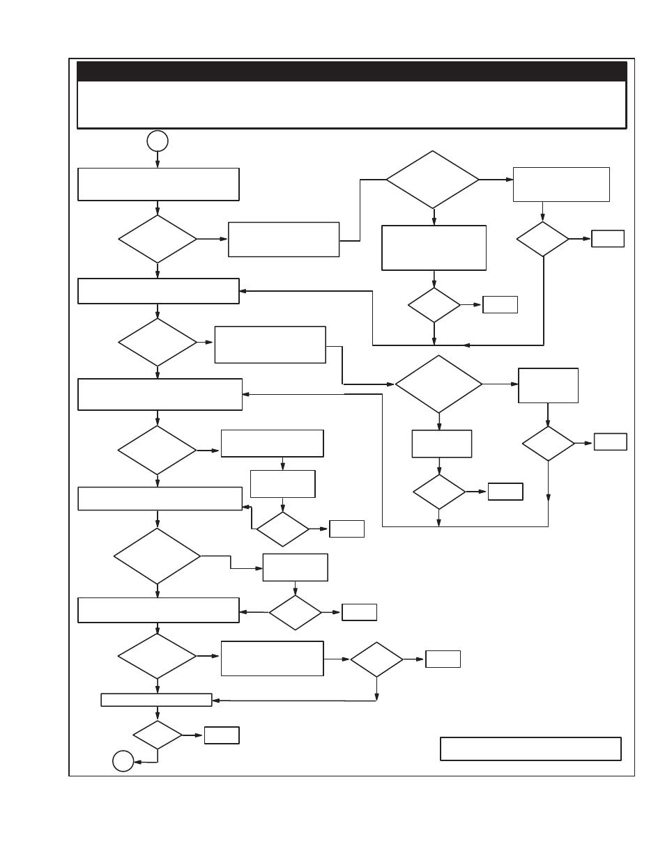
5:9
Replace
Control
Transformer
Check for 24VAC between
pins 481 and 482 of the
regulator board.
3B
Remove power from drive and check
for cotinuity between terminals 32
and 132.
Is there
continuity?
Check for 24VDC between terminal 132
and PIN 139 (COM).
Is
Voltage
Present?
While pressing start button, check for
24VDC between terminal 38 and Pin
139 (COM).
Is
Voltage
Present?
Check to see if Jumper J9 on the reguĆ
lator board has been cut or removed.
Has
jumper
been cut or
removed?
With AĆC power removed, check contiĆ
nuity between Pins 39 and 139.
Is there
continuity?
Replace regulator board.
Fixed?
Done
No
Yes
No
No
3C
Yes
Check for a motor therĆ
mostat or a jumper wired
to terminals 32 and132.
Is there a
thermostat/jumper
wired there?
Thermostat or jumper
is malfunctioning, corĆ
rect the problem.
Yes
No
Wire the motor thermoĆ
stat to terminals 32 and
132. If motor has no therĆ
mostat, install a jumper.
Fixed?
No
Yes
Done
No
Is
voltage
present?
Fixed?
Done
Yes
No
Yes
No
Replace regĆ
ulator board
Fixed?
No
Yes
Done
Yes
There is a problem with
the start/stop circuitry.
No
Yes
Correct the
problem.
Fixed?
Yes
Done
No
Correct the
problem.
Fixed?
Yes
Done
No
Coil of FM contactor is
open. Replace FM conĆ
tactor.
No
Fixed?
Yes
Done
No
Yes
Yes
Yes
Done
Fixed?
Note: #1: Contact local sales/service office.
DANGER
THE FOLLOWING CHECKS AND PROCEDURES REQUIRE THE POWER TO BE ON. EXERCISE EXTREME
CAUTION AS HAZARDOUS VOLTAGE EXISTS. FAILURE TO OBSERVE THIS PRECAUTION COULD
RESULT IN SEVERE BODILY INJURY OR LOSS OF LIFE.
Figure 5Ć6. Motor Doesn't Start. (Continued)