Power off inspection, Motor ground check, 50 hertz operation – Rockwell Automation MinPak Plus DC Drive User Manual User Manual
Page 25: 230 volt aćc applications, Horsepower - current scaling
4:2
DANGER
ONLY QUALIFIED ELECTRIĆ
CAL PERSONNEL FAMILIAR
WITH THE CONSTRUCTION
AND OPERATION OF THIS
EQUIPMENTAND THE HAZĆ
ARDS INVOLVED SHOULD
INSTALL, ADJUST AND/OR
SERVICE THIS EQUIPMENT.
READ AND UNDERSTAND
THIS MANUAL IN ITS ENTIREĆ
TY BEFORE PROCEEDING.
FAILURE TO OBSERVE THIS
PRECAUTION COULD REĆ
SULTIN SEVERE BODILY
INJURY OR LOSS OF LIFE.
DANGER
THIS EQUIPMENT IS AT LINE
VOLTAGE WHEN AĆC POWER
IS CONNECTED. DISCONĆ
NECTAND LOCKOUTALL
UNGROUNDED
CONDUCĆ
TORS OF THE AĆC POWER
LINE. FAILURE TO OBSERVE
THESE
PRECAUTIONS
COULD RESULTIN SEVERE
BODILY INJURY OR LOSS OF
LIFE.
Power Off Inspection
NOTE: These procedures assume
that the AĆC incoming line is locked
off and that the load is uncoupled
from the motor.
Inspect the Controller and
modification kits for possible
physical damage or improper
connections. Electrical connections
between the modification kits and
the Regulator are made via box
connectors over board pins. Before
inserting the kits, verify that the
mating pins are straight and
parallel. Only one pin will fit in each
box connector. All kits are to be
securely fastened to the regulator
board by the screws provided.
Verify the wiring of the operator's
station and wiring to the Drive. All
wire connections should be made
with sufficient bare wire to make a
good electrical connection. The
removal of an excessive length of
insulation may needlessly expose
conductors with the possibility of
shorts or safety hazards resulting.
Motor Ground Check
The DĆC Motor frame and conduit
box should be connected to a good
earth ground per the motor
instruction manual.
Verify that there is no path to
ground in either the DĆC Motor
armature circuit, the shunt field
circuit or the thermostat circuit.
Connect one lead of an ohmmeter
to the motor frame and the other
lead to the two armature leads, the
two field leads and to the two
thermostat leads. If a reading of less
than 100,000 ohms is observed, a
ground condition exists and MUST
be cleared before power is applied.
CAUTION: A meggar may be
used for this motor ground
check, but all conductors beĆ
tween the motor and the controlĆ
ler must be disconnected. FailĆ
ure to observe this precaution
could result in damage to, or deĆ
struction of, the equipment.
50 Hertz Operation
When the Drive is used in 50 hertz
applications, it is necessary to clip
two resistors on the Regulator
Board. These resistors are located
at grid AF4 to AF10 and AA63 to
AA69.
230 Volt AĆC
Applications
For 230 VAC applications, the
FlexPak Plus Regulator must be
modified by clipping jumpers J6
and J5. See Figure 4Ć1. This
modification has probably been
made at the factory upon Model
Number specification, however, this
should be verified. Clip both sides
of the jumpers to ensure a clean
circuit break.
Horsepower - Current
Scaling
Since a MinPak Plus Drive covers a
wide range of horsepower ratings
(see Table 4Ć1), it is necessary to
scale the Drive for the application
motor. The Current Scaling Jumper
on the Regulator Board must be set
for the specific motor full load
current rating. Locate the nameplate
on the drive motor and then note
the fullĆload current. If current is not
shown on the nameplate, refer to
Table 4Ć1. Relate the left or center
columns in Table 4Ć1 with known
motor data. Read across to the right
column marked "Motor Current".
This value indicates the proper
jumper connection to make on the
Regulator Board where a
corresponding number is etched on
the Printed Circuit Board.
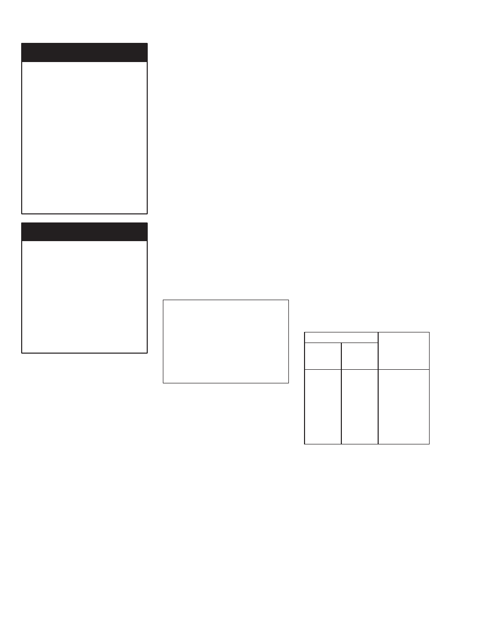
Table 4Ć1. Current Feedback
Scaling
Motor HP
115 VAC 230 VAC
Motor
Current/PIN
Connections
1/4
1/2
2.5A
1/3
3/4
3.7A
1/2
1
5.0A
3/4
1 1/2
7.5A
-
2
10.0A
-
3
15.0A
-
5
25.0A
Refer to Figure 4Ć2 to select the
appropriate current scaling
connection. Place the current
scaling jumper on the proper
connection. NOTE: Do not move the
jumper if it is connected to the
proper connection.
If the jumper must be reconnected,
carefully lift it straight up and off the
connector. Slide the jumper straight
down over the proper connection.