Rockwell Automation MinPak Plus DC Drive User Manual User Manual
Page 38
5:7
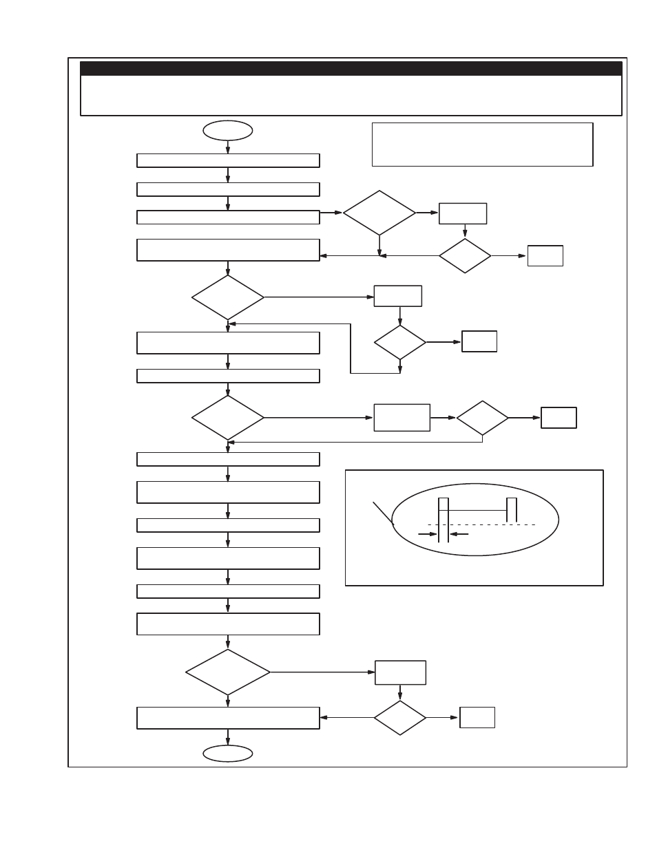
Remove AĆC power at disconnect.
Remove leads A1, A2
Check motor leads A1 and A2 for grounds
Verify connection of transformer leads H1 to
51 and H2 to 52
Are
they wired
correctly?
Place the common of ohmmeter on terminalā
7, andācheckāforāa short at terminals L1āandāL2.
Reverse the leads and repeat the test.
Were
any shorts
found?
An Oscilloscope is needed for further testing.
Leave motor leads disconnected and set up
drive as a voltage regulator.
Remove the gate firing connector.
Place oscilloscope leads on pins G1 and L1,
then apply power.
Start the drive and monitor the waveform.
Repeat this test for the following set of pins:
G2 L2, G3 47 and G4 47.
Do the
waveforms
match Figure
FC1?
Possible power cube breaking done under
load, see note #1
End
DANGER
SOME OF THE FOLLOWING CHECKS AND PROCEDURES REQUIRE THE POWER TO BE ON. EXERCISE
EXTREME CARE AS HAZARDOUS VOLTAGE EXISTS. FAILURE TO OBSERVE THIS PRECAUTION COULD
RESULT IN SEVERE BODILY INJURY OR LOSS OF LIFE.
Start
No
Correct
Problem
Fixed?
Done
Replace the
power cube
Fixed?
Done
Yes
Yes
Replace
Regulator
Fixed?
Yes
No
Note #1: Contact local sales/service office.
*Ground conditions = 500 KĆOhms or less to ground.
Yes
No
No
Typical Scope Reading Gate Pulses
G to K GĆWHT(+), KĆRED(Ć)
Done
Figure FC1
Yes
*
No
Yes
Any
Grounds
Found
?
Repair
Grounds
Fixed?
No
No
Done
Yes
No
Yes
OV
16.7 M.S.
Figure 5Ć5. Fuse Blows After Start.