Rockwell Automation MinPak Plus DC Drive User Manual User Manual
Page 16
3:5
DANGER
THE USER IS RESPONSIBLE
FOR CONFORMING TO THE
NEC AND ALL OTHER APPLIĆ
CABLE LOCAL CODES WITH
RESPECT TO WIRING PRACĆ
TICES, GROUNDING, DISĆ
CONNECTS AND OVERCURĆ
RENT PROTECTION ARE OF
PARTICULAR IMPORTANCE.
FAILURE TO OBSERVE THIS
PRECAUTION COULD REĆ
SULT IN SEVERE BODILY
INJURYOR LOSS OF LIFE.
DANGER
THIS EQUIPMENT IS AT LINE
VOLTAGE WHEN AĆC POWER
IS CONNECTED.
DISCONĆ
NECT AND LOCKOUT ALL
UNGROUNDED
CONDUCĆ
TORS OF THE AĆC POWER
LINE. FAILURE TO OBSERVE
THESE PRECAUTIONS COULD
RESULT IN SEVERE BODILY
INJURYOR LOSS OF LIFE.
Ground the Controller and
Enclosure, the Motor and the
Operator's Control Station.
DANGER
CONNECT
THE
GROUND
WIRE BROUGHT IN WITH THE
INCOMING AĆC POWER LINE
TO
THE
CONTROLLER
GROUND POINT. CONNECT
AN APPROPRIATE EQUIPĆ
MENT GROUNDING CONDUCĆ
TOR UNBROKEN FROM THE
THE CONTROLLER GROUND
POINT, THE MOTOR FRAME,
THE TRANSFORMER ENCLOĆ
SURE IF USED, THE CONĆ
TROLLER ELECTRICAL ENĆ
CLOSURE, THE WIRING CONĆ
DUITS, AND THE OPERAĆ
TOR'S CONTROL STATION TO
AN APPROPRIATE GROUNDĆ
ING ELECTRODE. FAILURE
TO OBSERVE THESE PREĆ
CAUTIONS COULD RESULT IN
SEVERE BODILYINJURYOR
LOSS OF LIFE.
1. Locate the Controller ground
point provided.
2. Run asuitable equipment
grounding conductor unbroken
from the Controller ground point
(see step 1) to the plant ground
(grounding electrode). A ring
lug is recommended at the
ground point.
3. Connect asuitable grounding
conductor from each conduit to
this controller ground point.
4. Connect asuitable equipment
grounding conductor to the
motor frame, the transformer
enclosure if used, and the
controller enclosure. Run this
conductor unbroken to the
grounding electrode.
5. Connect the GND
(green/ground) wire brought in
with the incoming AĆC power line
to the controller ground point.
Ground the Optional
Faceplate
A ground wire is supplied as
standard with each Faceplate.
Connect the ground wire to abolt
on the underside of the cover and to
the controller chassis. Refer to
Figure 3Ć3A.
NOTE: Since the green wire is fixed
by the user on a faceplate bolt, the
installation should be performed
when the faceplate is fitted.
Figure 3Ć3A. Cover Ground Wire
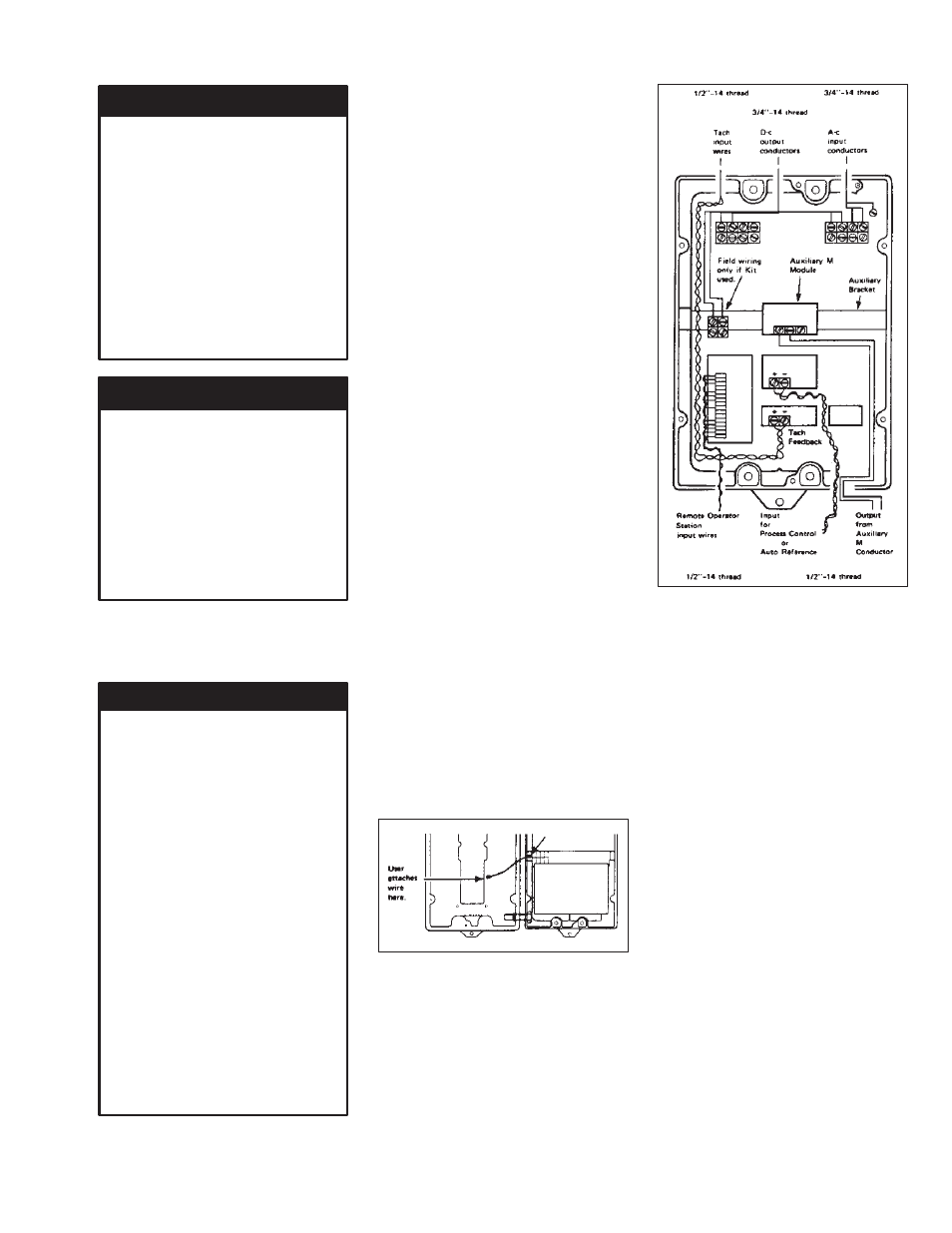
General Wiring Practices
The Controller is designed for
Tachometer input wires, AĆC and
DĆC power entry at the top and
control and signal wiring to enter
from the bottom. See Figure 3Ć4.
Figure 3Ć4. Chassis Wells, Wire
Routing
Reference signal wiring should be
run in a separate steel conduit
isolated from all AĆC and DĆC power
and control. All reference signals
should be wired with either twisted
double or twisted triple conductor
wire, 2 twists per inch, stranded
copper, AWG No. 16, 600 VAC
rated, polyĆvinyl chloride insulation,
with a temperature range of 40 -
105_C (104 - 221_F). Signal wires
should not be run in parallel with
high voltage or electrically noisy
conductors. Always cross such
conductors at 90_.
Tachometer Feedback, Instrument
Interface and Voltage/Tachometer
Follower signal wiring should be run
in a separate conduit isolated from
all AĆC and DĆC power and logic
control. Wiring should be the same
as for the reference signals above.
For mounting with external
contactors and solenoids, coils