Regulation mode selection, Power on – Rockwell Automation MinPak Plus DC Drive User Manual User Manual
Page 26
4:3
J8
COM
T A
87
86
2.5
3.7
5
7.5
10
15
25
AMPS
I
FDBK.
RED
45
ARM.
FDBK.
47
FDBK.
G2 L2
G3 47 G4 47
L1 G1
192193
COM
J2
MODE
SELECTION
JUMPER
REGULATION
MODE
CONNECTIONS
CURRENT
SCALING
JUMPER
C
CURRENT
SCALING
JUMPER
CONNECTIONS
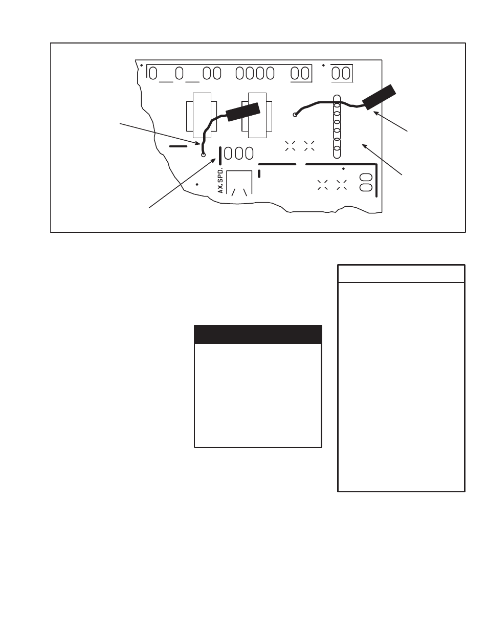
Figure 4Ć2. Drive Current Scaling Setup.
Regulation Mode
Selection
The MinPak Plus Drive has three
modes of regulation; A = Speed
Regulation by Armature Voltage, T
= Speed Regulation by Tachometer
or C = Counter EMF Feedback.
This initial SetĆup Procedure will be
conducted in the Armature Voltage
Mode with the selection jumper set
on pin A on the Regulator Board
even though a tachometer may be
used in the final system
configuration. Refer to Figure 4Ć2
and set the Regulation Mode
jumper to the A position.
Power On
Once all the preliminary checks
have been completed, apply AĆC
Power to the Drive. Carefully
observe all cautions and warnings.
DANGER
THE FOLLOWING CHECKS
AND PROCEDURES REQUIRE
THE POWER TO BE ON.
EXERCISE EXTREME CARE
AS HAZARDOUS VOLTAGE
EXISTS.
FAILURE TO OBĆ
SERVE THIS PRECAUTION
COULD RESULT IN SEVERE
BODILY INJURY OR LOSS OF
LIFE.
WARNING
FOR DRIVES WITH A FIELD
SUPPLY KIT, IF THE CIRCUIT
BREAKER HAS TRIPPED OR
THE POWER FUSES HAVE
BLOWN, THE FIELD SUPPLY
KIT AND ITS WIRING MUST
BE INSPECTED FOR DAMĆ
AGE. AFTER REĆAPPLYING
POWER TO THE DRIVE, THE
FIELD VOLTAGE MUST BE
CHECKED FOR PROPER
VOLTAGE AT MOTOR TERMIĆ
NALS F1 AND F2. IF THIS
VOLTAGE IS BELOW 90% OF
THE SPECIFICATION VOLTĆ
AGE, THE DRIVE MUST NOT
BE STARTED UNTIL PROPER
VOLTAGE
IS
OBTAINED.
FAILURE TO OBSERVE THIS
PRECAUTION COULD REĆ
SULT IN BODILY INJURY.
Verify that the F1 - F2 Field Supply
Voltage is the same as the motor
nameplate voltage if the Field
Supply Kit is used. The field supply
is standard on 3 thru 5 HP drives.
Check and verify control power
voltages before proceeding. See
Table 4Ć2 for nominal values.