Rockwell Automation MinPak Plus DC Drive User Manual User Manual
Page 21
3:10
Wire the DĆC Motor to the
Controller
1. Size the motor armature circuit
conductors for the specific
controller rating and according
to applicable codes.
2. Run the DĆC motor armature
leads and the shunt field supply
leads (if a permanent magnet
field motor is not used). See
Figure 3Ć8 for the Motor
Armature Circuit Connection.
Refer to Wire the Field Supply"
in this manual for field supply
connections.
Install the Field Supply
The Field Supply Kit provides
fullĆwave field excitation for
shuntĆwound DĆC motors. It may be
optionally applied to controllers
from 1/4 thru 1 1/2 HP. (It is a
standard feature for 3 and 5 HP
MinPak Plus controllers.)
The Kit is an assembly consisting of
a terminal block (F1, F2), a field
power cube, two wiring harnesses,
bracket support and mounting
hardware. The user provides the
F1/F2 conductors to the drive motor.
No other equipment is required.
To install the Kit, follow these
procedures.
Step 1 - Mount Field Kit
a. Remove screws from 1TB.
b. Remove screws from the support
bracket.
c. Remove screw leads 32 and 132
from 2TB.
d. Remove the support bracket
from the unit.
e. Mount the Field Supply Kit onto
the unit.
f. Reinstall leads 32 and 132 onto
2TB.
g. Mount 1TB to the Field Supply
Kit.
Wire the Field Supply
DĆC field supply voltage and
maximum field amperes are listed in
Table 2Ć1.
Step 1 - Wire Field Supply Power
Cube
Wire from the field supply power
cube to terminals 51 and 52 on 2TB
as shown in Figure 3Ć9.
AĆC
AĆC
+
2 TB
51
52
F1 F2
3 TB
To
F1, F2
on motor
Figure 3Ć9. Connecting Field
Supply.
Step 2 - Ro ute Wires and F1/F2
Connection
The userĆsupplied field wiring
conductors should be drawn into
the chassis. Route them as
indicated in Figure 3Ć3. Move them
to the upper screws on 3TB and
connect F1/F2 according to the
label or Figure 3Ć9.
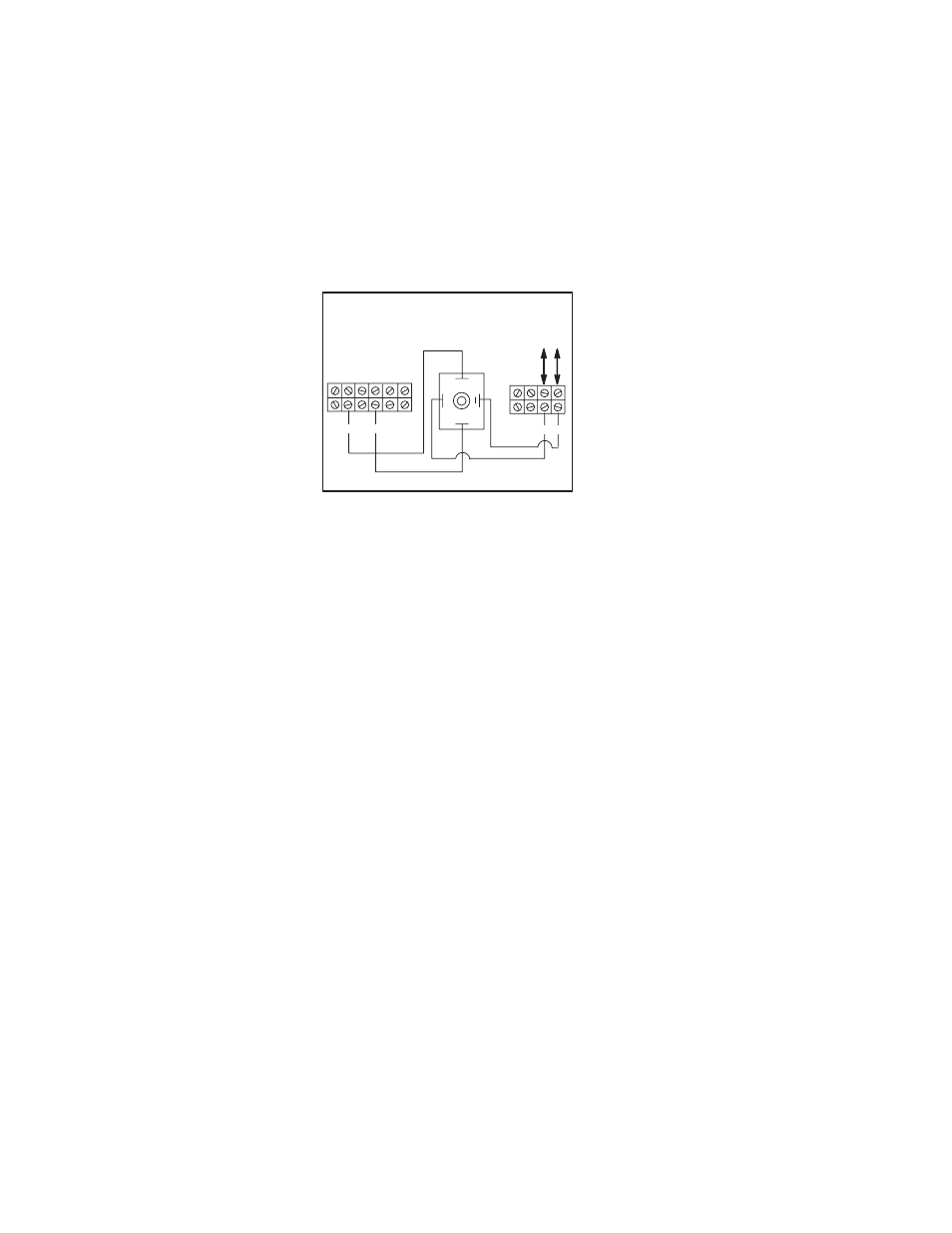
Wire the Speed Reference
Circuit
When only a Manual Operator's
Speed Pot Reference function is
utilized, the circuit shown in Figure
3Ć10 should be followed.
In this configuration (see Figure
3Ć10), the J4 jumper on the
Regulator Board is NOT to be cut,
the reference input is through
terminal 426 to the LVTU. The J4
Jumper is only removed when the
reference is brought in to terminal
126. Lead 126 is not to be taken
outside of the cabinet as it is not
buffered.
Reliance offers four Reference Kits
for Automatic Process Following.
These kits are:
1. Voltage/Tachometer Follower Kit,
M/N 14C223.
2. Instrument Interface/Preset
Speed Kit, M/N 14C222.
3. Dancer Follower Kit,
M/N 14C230.
4 Dancer Position kit, M/N 14C233.
These Kits can be used as
Automatic Reference Followers with
or without a Manual optional
function. If used without a Manual
option function, as described
above, the reference circuit for
these kits is setĆup as shown in
Figure 3Ć11. If the Automatic
Reference Kits are to be used with a
Manual optional function as
described above, the reference
circuit for these kits is setĆup as
shown in Figure 3Ć12.