Digital in 3 (reset), Digital in 4 (run/jog), Digital in 5 (fl) – Rockwell Automation GV3000/SE AC Drive ControlNet Network Communication Board, M/N 2CN3000 User Manual
Page 68: Digital in 6, Digital in 7, Digital in 8, P.066, Motor kw, P.069, Encoder counts
4-6
GV3000/SE AC Drive ControlNet Network Communication Option Board
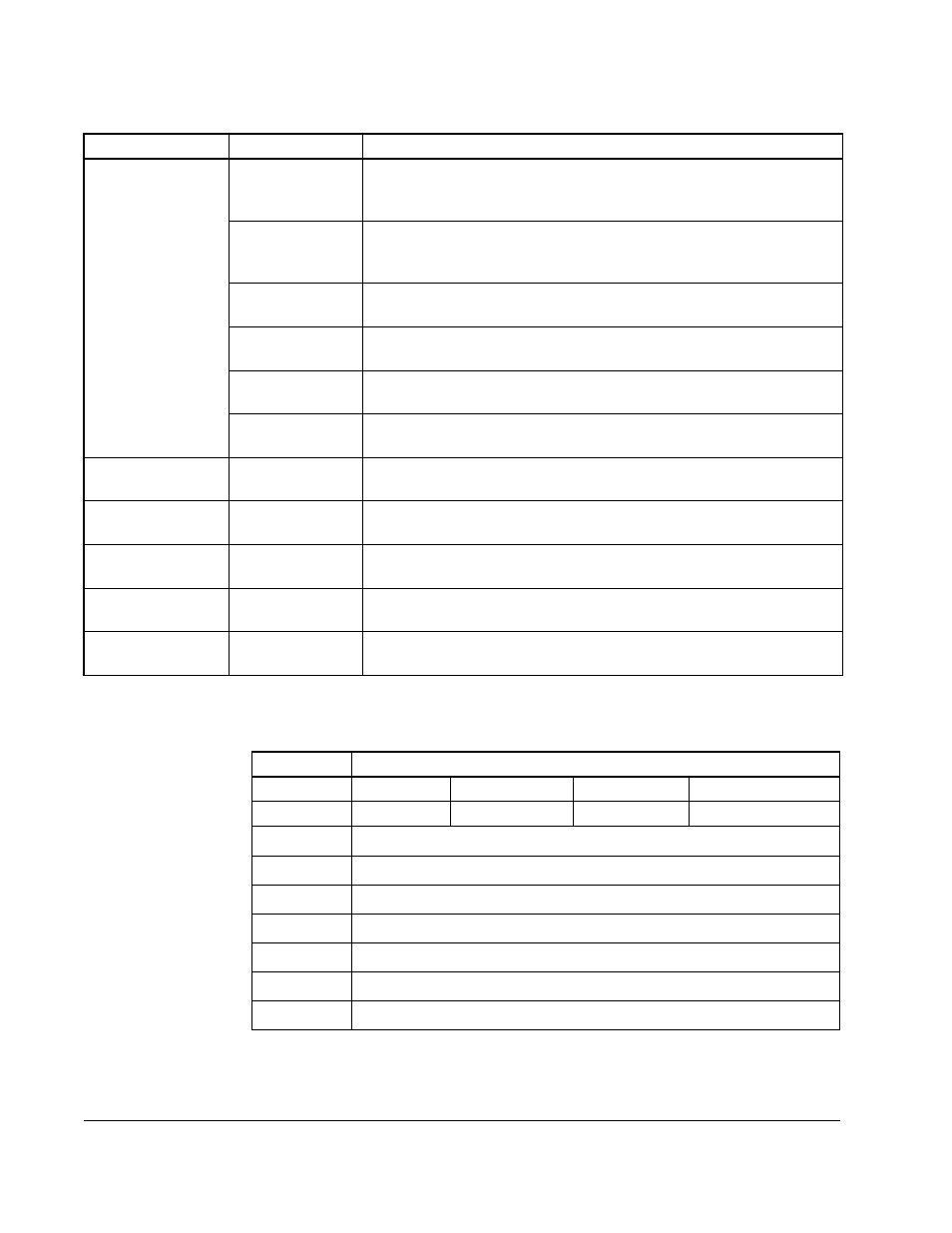
Table 4.5 explains the values that are available for words 2 - 5.
10
Digital In 3
(Reset)
This bit indicates the status of digital input 3.
11
Digital In 4
(Run/Jog)
This bit indicates the status of digital input 4.
12
Digital In 5 (FL)
This bit indicates the status of digital input 5.
13
Digital In 6
This bit indicates the status of digital input 6.
14
Digital In 7
This bit indicates the status of digital input 7.
15
Digital In 8
This bit indicates the status of digital input 8.
Word 1 –
Speed Reference
—
This word indicates the speed reference being used by the drive.
Values range from
±4095.
Word 2 –
Selected Output 1
—
This word indicates the value selected in parameter P.066. See table
4.5.
Word 3 –
Selected Output 2
—
This word indicates the value selected in parameter P.067. See table
4.5.
Word 4 –
Selected Output 3
—
This word indicates the value selected in parameter P.068. See table
4.5.
Word 5 –
Selected Output 4
—
This word indicates the value selected in parameter P.069. See table
4.5.
Table 4.4 – Scheduled Drive Feedback Data (Continued)
Word:
Bit:
Description:
Table 4.5 – Signals That Can Be Displayed in Words 2 - 5
Value:
Parameters
P.066
P.067
P.068
P.069
0
Motor KW
Motor Torque
Power Factor
Encoder Counts
1
Speed reference limited output
1
2
Speed reference plus OCL output
1
3
4
Speed error
1
5
Speed PI output
1
6
OCL feedback
1
7
OCL error
1