Network option board, Refer to figure 2.12 for component locations – Rockwell Automation GV3000/SE AC Drive ControlNet Network Communication Board, M/N 2CN3000 User Manual
Page 36
2-24
GV3000/SE AC Drive ControlNet Network Communication Option Board
Step 4.
Install the ControlNet Option Board in the Keypad Bracket
Refer to figure 2.12 for component locations.
Step 4.1 Remove the ControlNet option board from its anti-static wrapper.
Step 4.2 Align the key on the connector of the ControlNet option board ribbon cable
Step 4.3 Align the ControlNet option board on the four mounting tabs on the keypad
Step 4.4 Fasten the right side of the ControlNet option board to the keypad bracket.
Use the two metal M3 screws and lock washers for grounding.
Important: You must use the lock washers to properly ground the option board.
Improper grounding of the option board can result in erratic operation of
the drive.
Step 4.5 Fasten the left side of the ControlNet option board to the keypad bracket
Step 4.6 Realign the 26-conductor ribbon cable connector with the Power Supply
board connector inside the slot in the keypad support bracket. Carefully
press the ribbon cable connector in until the retaining clips lock it into place.
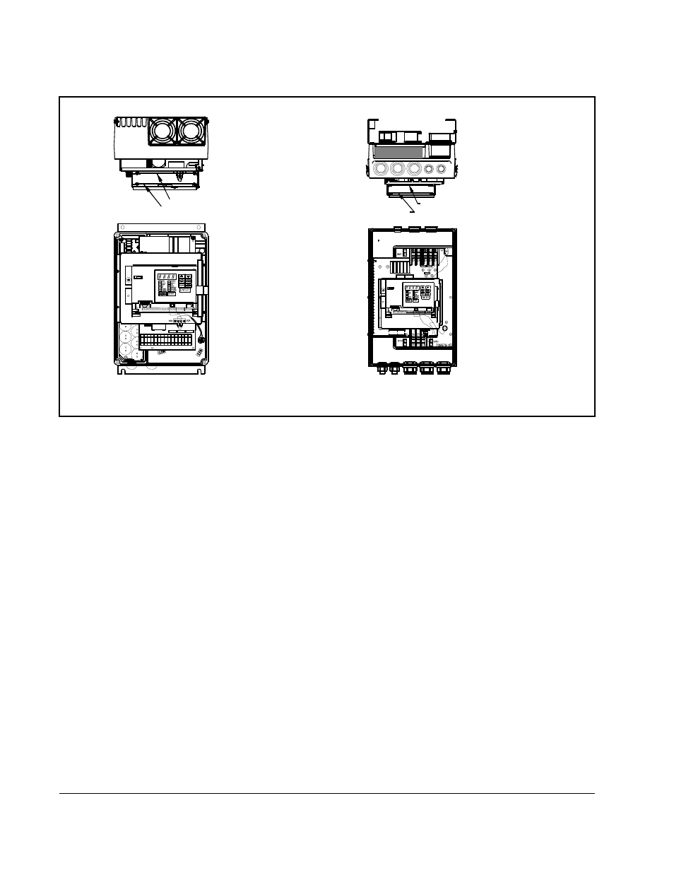
Figure 2.12 – GV3000/SE Drive (15 to 25 and 25 to 60 HP @ 460 VAC)
Network Option Board
Regulator Board
Front View
Top View
15 to 25 HP @ 460 VAC
Network Option Board
Regulator Board
Front View
Top View
25 to 60 HP @ 460 VAC