Rockwell Automation 57C329 Remote I/O Communications, AutoMax User Manual
Page 49
3Ć23
Step 5.
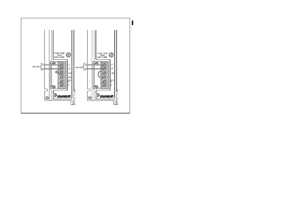
Refer to figure 3.21 and use the following procedure to
connect input power to the Remote I/O Head:
240
240 VAC INPUT POWER
120 VAC INPUT POWER
M/N 57C328, M/N 57C329, and M/N 57C330
Figure 3.21 Ć 120 VAC or 240 VAC Input Power Connections
a.) Using a screwdriver, remove one of the screws from
the plastic guard covering the terminal strip and slide
the guard to the left to expose the terminals.
b.) Turn off and lock out or tag all sources of incoming
power. Make certain that no voltage is present on the
wires that will be used to provide 120 VAC or 240 VAC
input power.
c.) Using 14 AWG wire, connect the input power wires to
terminals L1 and L2.
d.) Connect the jumper wire to the corresponding
terminal, either 120 or 240 volts.
e.) Slide the guard back to cover the terminal strip and
replace the screw.
Step 6.
Set the drop number (1Ć7) of the Remote I/O Head using
the thumbwheel switch on the faceplate.
The drop number setting is recognized only at power up.
Therefore, make sure each drop on the network has a
unique drop number before power is applied. If more than
one drop is given the same drop number, transmission
collisions will occur on the line.