Rockwell Automation 57C329 Remote I/O Communications, AutoMax User Manual
Page 128
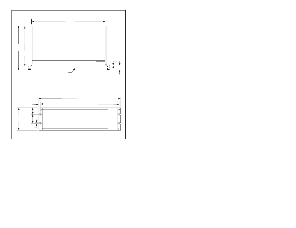
KĆ10
17.53
9.72
REF.
8.98
Cover
.12
.86
TOP VIEW
FRONT VIEW
19.00
18.18
5.23
1.49
2.25
.250
(4) PL.
.41
Figure K2.3 Ć FiberĆOptic Rack Mounting Dimensions
Step 3.
Plug each transceiver into any empty slots in the rack.
Verify that on the transceivers at the extreme ends of the
rack, a jumper has been connected between terminals 3
and 4 on the sixĆscrew terminal block.
Step 4.
Use twistedĆpair wire (as specified in Appendix G) to
make all signal connections between transceivers as
shown in figure K2.4. To improve network serviceability,
make the signal connections between transceivers on a
separate terminal strip as shown in figure K2.5. Use a
standard terminal strip for these connections.
This manual is related to the following products: