Rockwell Automation 57C329 Remote I/O Communications, AutoMax User Manual
Page 38
3Ć12
Step 4.
Crimp the center contact by holding the cable in place
and closing the tool handles until the rachet releases.
Step 5.
Remove the crimped contact from the dies.
Step 6.
Verify that the shield braid wire does not touch the center
contact. Refer to figure 3.11.
SUPPORT SLEEVE
OF CONNECTOR
CRIMPED CONTACT
Figure 3.11 Ć Connector Installation Step 6 for RGĆ59/U Cable
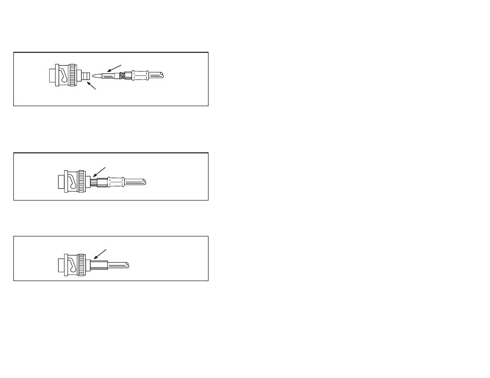
Step 7.
Insert the crimped center contact into the BNC connector
body until the cable dielectric butts against the dielectric
inside the connector body. The flared braid will then fit
around the support sleeve of the connector body. See
figure 3.12.
BRAID OVER CONNECTOR
SUPPORT SLEEVE
Figure 3.12 Ć Connector Installation Step 7 for RGĆ59/U
Step 8.
Slide the ferrule forward over the shield braid wire and
support sleeve until the ferrule butts against the shoulder
on the connector body. See figure 3.13.
FERRULE SLID FORWARD
OVER BRAID AND SUPPORT
SLEEVE
Figure 3.13 Ć Connector Installation Step 8 for RGĆ59/U Cable
Step 9.
Place the ferrule on the anvil of the die assembly so that
the shoulder on the connector body butts against the die.
See figure 3.14.