Rockwell Automation 57C329 Remote I/O Communications, AutoMax User Manual
Page 123
KĆ5
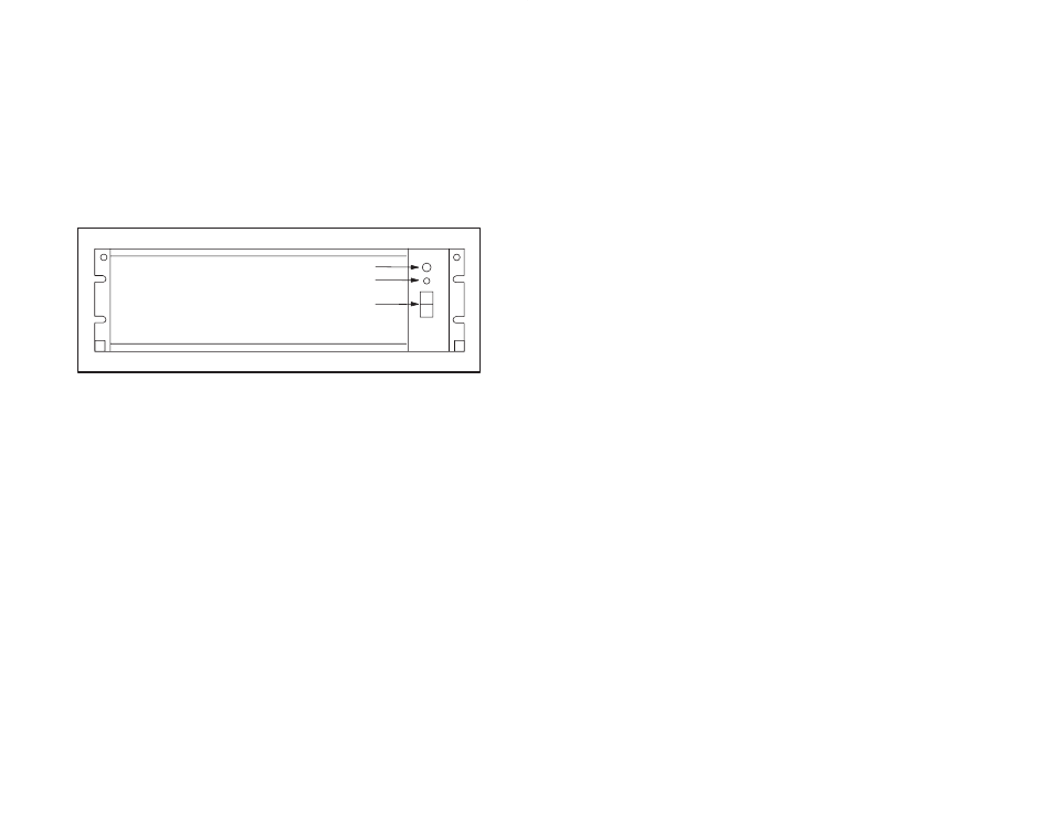
The rack is a 19Ćinch clear anodized aluminum enclosure with a
transparent plastic front panel. The rack contains a 115/230VAC
power supply and 10 slots for transceivers. Each transceiver
receives operating power through plug connections at the bottom of
each slot in the rack. TransceiverĆtoĆtransceiver wiring and
connection to the fiberĆoptic link is done through openings in the
back of the rack.
The Power Supply consists of a 115/230 to 14V AC transformer
connected to a standard IECĆstyle line cord. On the back of the
rack, there is a switch wired to the transformer to allow switching the
primary from 115 to 230V AC. The faceplate of the Power Supply
contains an ON/OFF rocker switch and a 1.25 amp fuse. A builtĆin
indicator in the ON/OFF switch will illuminate to indicate the
presence of power. See Appendix E for the Power Supply
schematic.
Fuse Holder
Power Status LED
Power Switch
Figure K1.3 Ć FiberĆOptic Rack and Power Supply
K1.2.5
RackĆMounted Transceiver
The RackĆMounted Transceiver (M/N 57C367) is simply the
StandĆAlone Transceiver (M/N 57C365) attached to an adapter plate
which allows it to be mounted in the Transceiver Rack (M/N
57C368). See figure K1.4.
The adapter faceplate contains one green LED which, when lit,
indicates the transceiver is receiving power. Two captive screws on
the faceplate secure the transceiver to the rack.
A fourĆscrew terminal block is provided on the back of the adapter
for transceiverĆtoĆtransceiver data transmission via twistedĆpair wire.
A 2Ćpin plug on the back of the adapter provides connection to the
rack backplane for input power. The RackĆMounted Transceiver is
shipped with the connections made between the fourĆscrew terminal
block and plug on the back of the adapter and the sixĆscrew
terminal block on the transceiver. A jumper between terminals 3
and 4 on the sixĆscrew terminal block is used to connect a builtĆin
120 ohm terminating load between terminals 1 and 2. This jumper
must be connected on transceivers at the extreme ends of the rack.
Receive and transmit ports labeled R" and T", respectively, are
provided on the back of the transceiver for connection to the
fiberĆoptic link with the StandĆAlone Transceiver. The transceiver is
shipped with dust caps covering the fiberĆoptic ports. The dust caps
should not be removed until the fiberĆoptic cables are installed, and
should be replaced if the cables are disconnected, to prevent dust
accumulation and the resulting loss of the signal integrity. The green