Rockwell Automation 57C329 Remote I/O Communications, AutoMax User Manual
Page 46
3Ć20
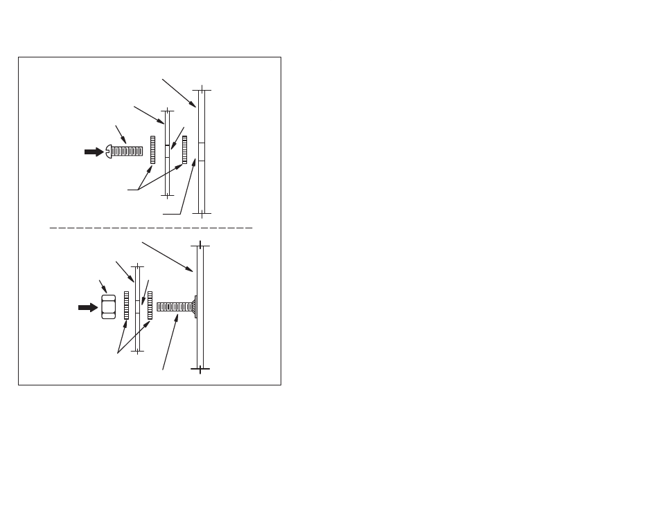
Step 2.
Mount the Remote I/O Head on the panel and attach it
securely with #10 (M5) bolts or studs. Examples of
attaching the Remote I/O Head to the mounting surface
are shown in figure 3.18.
Й
Й
Й
Й
Й
Й
Й
Й
Й
Й
ЙЙ
ЙЙ
ЙЙ
ЙЙ
ЙЙ
ЙЙ
ЙЙ
ЙЙ
Й
Й
Й
Й
Й
Й
Й
Й
Й
Й
Й
Й
Й
Й
Й
Й
Й
Й
TAPPED HOLE
STARWASHER
BOLT
MOUNTING FLANGE
MOUNTING FLANGE
MOUNTING SURFACE
BACK PANEL
NUT
.218" DIA.
.218" DIA.
STARWASHER
WELDED STUD
Figure 3.18 Ć Mounting Examples
Step 3.
Using figure 3.19, locate the two No. 10 studs provided on
the Remote I/O Head for grounding purposes. The
Remote I/O Head must be properly grounded to minimize
personnel hazard and to ensure proper operation. The
ground path, when using a 1KVA transformer, should have
less than 10 milliohms resistance. The grounding wire
must be a minimum size of 14 AWG. The insulation should
be green for U.S.A. applications.