Rockwell Automation 57C329 Remote I/O Communications, AutoMax User Manual
Page 120
KĆ2
1
2 3
4
5
6
7 8
9 10 P/S
Remote I/O Communications Module
AutoMax Rack
Drop Cable (M/N 57C366)
Hub (Rack/Power
TwistedĆ
Pair Wire
FiberĆOptic Cable
StandĆAlone Transceiver
(M/N 57C365)
Drop Cable
(M/N 57C366)
AutoMax Rack containing
Supply M/N 57C368
containing 10
transceivers
M/N 57C367)
Master
Remote I/O Head, Remote Drive
Balun
TwistedĆPair Wire
Tee Adapter
. . .
Terminating
Load
Coax
Cable
(Slave Drop)
(Slave Drop)
Interface Head or
Personal Computer containing
PC Link Interface module
Remote I/O Communications
Module or Shark Rack
containing Shark Interface Module
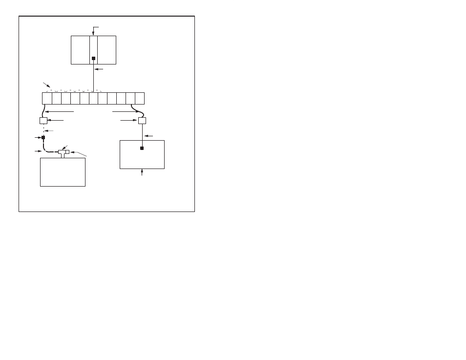
Figure K1.1 Ć FiberĆOptic Remote I/O Network
As shown in the above figure, a StandĆAlone Transceiver is required
at each slave drop on the network. A StandĆAlone Transceiver is
required at the master rack only when this rack and the hub cannot
be located together in the same cabinet. The transceiver performs
the optical conversion of electrical data signals from the Network
module to the network and the electrical conversion of optical data
signals from the network to the Network module.
Each drop is connected by a fiberĆoptic link to another transceiver
mounted in a rack. Up to 10 transceivers can be mounted in the
transceiver rack, also called a hub". All communication between
drops takes place in the transceiver rack. The optical signals
received by any transceiver in the rack are converted into electrical
signals and propagated to all other transceivers in the rack via
twistedĆpair wire connections. Each transceiver then converts the
electrical signals to optical signals and retransmits them to its
corresponding drop.