Selecting data format, Using binary data input, Selecting data format using binary data input – Rockwell Automation 2706 DL40 HARDWARE USER MANUAL User Manual
Page 86
Chapter 9
Using the Parallel Port
9 – 2
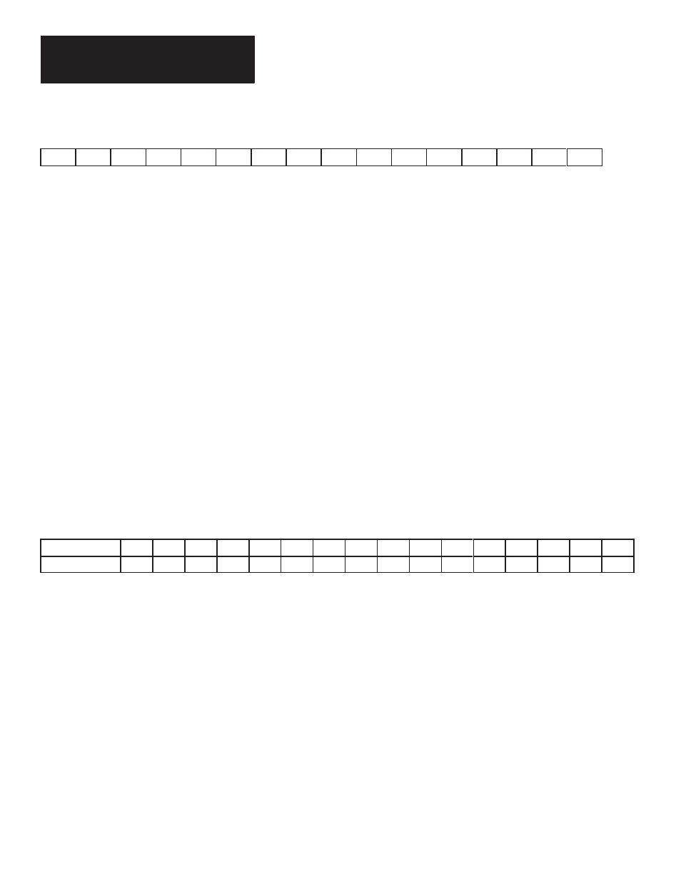
Table 9.A
Relative significance of each data line
D15
D14
D13
D12
D11
D10
D9
D8
D7
D6
D5
D4
D3
D2
D1
D0
MSB
LSB
The parallel port uses either the binary numbering system or the Binary
Coded Decimal (BCD) numbering system to transfer message numbers and
[CTRL][V]
(formatted) variables. It uses BCD or ASCII for
[CTRL][W]
(unformatted) variables. You must select which numbering system best suits
your needs, and then set the parallel port to the selected data format using the
Onboard Editor or Offline Programming Software.
Each numbering system, binary or BCD, has its own merits. Your choice will
often be based upon the format used by your controller. However, the use of
binary numbers to input variables allows you to use variable data in the range
of –32,768 to +32,767 (2’s complement binary). If you use BCD numbers to
input variable data, the variable may range in value from –9,999 to +9,999.
A data line may either be at ground level or have a voltage present. The
convention of having a voltage represent a value of 1 and ground
representing a value of 0, is known as High True Logic. The opposite
convention is called Low True Logic. You can set the DL40 to accept either
High True or Low True Logic using the Offline Programming Software.
Table 9.B shows the value of each data line.
Table 9.B
Binary Value of Data Lines
Data Line
D15
D14
D13
D12
D11
D10
D9
D8
D7
D6
D5
D4
D3
D2
D1
D0
Data Line Value
32768 16384
8192
4096
2048
1024
512
256
128
64
32
16
8
4
2
1
MSB
LSB
For example, assume the following logic levels appear as shown in
Table 9.C.
Selecting Data Format
Using Binary Data Input