Bit trigger run mode – Rockwell Automation 2706 DL40 HARDWARE USER MANUAL User Manual
Page 117
Chapter 10
Using Remote I/O
10 – 25
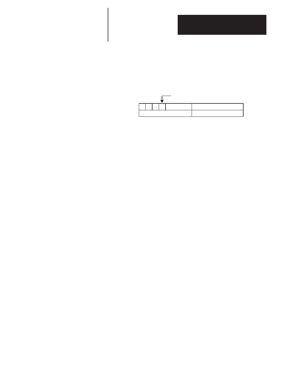
Return Clock or Date Data to PLC (Block Transfer Read)
Note: If Block Transfer Read
Length
is set to 0 in the PLC program, the
DL40 will return 2 words.
WORD 1
17 16 15
14
WORD 0
Block Transfer Read
File
Any Size Rack
Clock/Date Data Bit = 1
Diagnostic Code
Hour/Month
Minute/Day
Second/Year
Note: When sending Clock Data to a PLC from the DL40, the Acknowledge
Bit will never change state (go to 1) even if MSG ACK is set for that
message.
In the Bit Trigger Run Mode, each bit in the Bit Trigger Table that is set will
trigger a message. The position of a bit in the table corresponds to the
Message Number. Bit 0 (LSB) of word 1 corresponds to message number 1;
bit 1 in word 1 corresponds to message number 2.
The Bit Trigger Table has 2 sections, the Priority Section and the Round
Robin Section.
Note: With
1
/
4
rack, Bit Trigger Table must be either priority section or
round robin section. The length (in words) of the Priority Section is set in the
Programming Software. The length of the Round Robin Section is what is
left over (total table length minus the Priority Section length minus 1.) With
Discrete I/O, the length of the table is 1, 3, 5, or 7 words long depending on
rack configuration (
1
/
4
,
1
/
2
,
3
/
4
,
full). With 16 bits per word, the maximum
number of messages that can be triggered with discrete I/O is 112 (total for
priority and/or round robin messages). The total length of the Bit Trigger
Table for Block Transfer is 32 words. With 16 bits per word, the maximum
number of messages that can be triggered is 496. Both sections are in whole
words.
In addition, Priority Message Numbers can be sent.
Bit Trigger Run Mode