12 - dip switch settings, Chapter objections, Remote i/o units – Rockwell Automation 2706 DL40 HARDWARE USER MANUAL User Manual
Page 136: Dip switch settings, Chapter objections remote i/o units
Chapter
12
Chapter 12
DIP Switch Settings
Figure 12Table 12
12 – 1
Chapter 11
DIP Switch Settings
This chapter gives DIP switch settings for Remote I/O and Parallel Port
units.
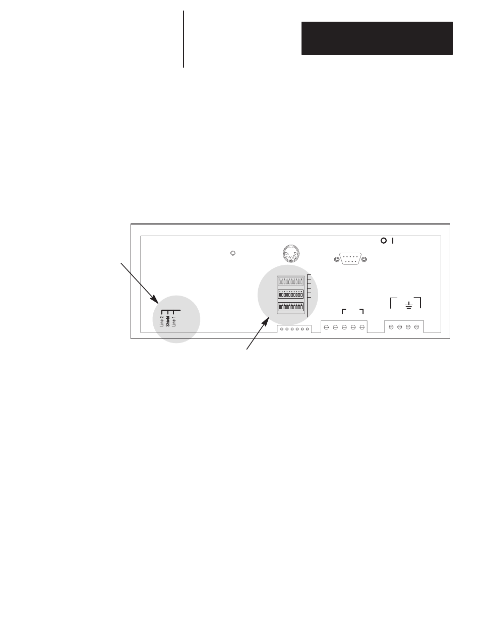
Three DIP switch banks are located on the back of the module. You can
access the DIP switches through a cutout, as shown below.
Figure 12.1
DIP Switch Locations
Allen-Bradley
Remote I/O Port
Location of DIP Switches
KEYBOARD
SW1
SW2
SW3
RS-485
REM
RES
ISO
GND
RELAY
N.O. N.C. COM
1 - 2 - 3 - 4 - 5 - 6
1 – E GND
2 – SHLD
3 – COMM
4 – CH A
5 – CH B
6 – TERM
RESET
AC PWR
VAC
HOT NEU
E.
GND
CHA
GND
PWR
RS-232
COMM
Switch Bank #1 (SW–1) sets the rack address.
Switch Bank #2 (SW–2) controls: Baud rate, Fast Reset Sequence, Block
Transfer, Last Chassis, Keyboard Type, Handshaking, Last State, Select
Enable.
Switch Bank #3 (SW–3) sets the serial address. The serial address refers to
the address used for triggers received from the serial RS–485 port or
computer keyboard.
Important: Remove power from the DL40 before setting any switch except
Select Enable, SW2–9. Select Enable can be switched with
power on. Switch settings are scanned only on power–up. The
new setting for Select Enable takes effect immediately. The new
settings for all other switches take effect when you power–up or
reset the DL40.
Chapter Objections
Remote I/O Units