Rockwell Automation 1763 MicroLogix 1100 Programmable Controllers User Manual User Manual
Page 235
Publication 1763-UM001D-EN-P - March 2011
System Loading and Heat Dissipation 233
Validating the System
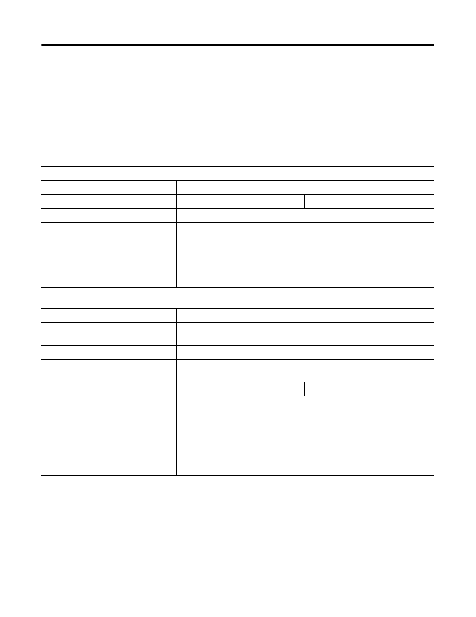
The example systems shown in the tables below are verified to be acceptable
configurations. The systems are valid because:
•
Calculated Current Values < Maximum Allowable Current Values
•
Calculated System Loading < Maximum Allowable System Loading
Validating Systems using 1763-L16AWA, 1763-L16BBB, or 1763-L16DWD
Maximum Allowable Values
Calculated Values
Current:
Current (Subtotal from Table on page 232.):
800 mA at 5V DC
700 mA at 24V DC
0 mA + 260 mA = 260 mA at 5V DC
120 mA + 180 mA = 300 mA at 24V DC
System Loading:
System Loading:
20.8 W
= (260 mA x 5V) + (300 mA x 24V)
= (1,300 mW) + (7,200 mW)
= 8,500 mW
= 8.50 W
Validating Systems using 1763-L16BWA
Maximum Allowable Values
Calculated Values
Current for Devices Connected to the +24V
DC Sensor Supply:
Sum of all sensor currents
200 mA at 24V DC
140 mA at 24V DC (example sensor value)
Current for MicroLogix Accessories and
Expansion I/O:
Current Values (Subtotal from Table ):
800 mA at 5V DC
700 mA at 24V DC
0 mA + 260 mA = 260 mA at 5V DC
120 mA + 180 mA = 300 mA at 24V DC
System Loading:
System Loading:
16.4 W
= (140 mA x 24V) + (260 mA x 5V) + (300 mA x 24V)
= (3,360 mW) + (1,300 mW) + (7,200 mW)
= 11,860 mW
= 11.9 W