Rockwell Automation 1763 MicroLogix 1100 Programmable Controllers User Manual User Manual
Page 160
Publication 1763-UM001D-EN-P - March 2011
158 Specifications
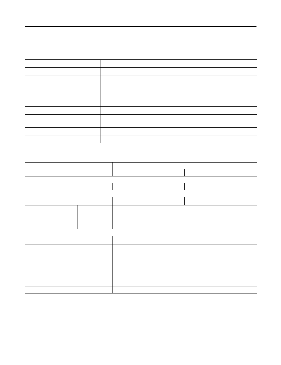
Analog Input Specifications
Description
1763-L16AWA, -L16BWA, -L16BBB, -L16DWD
Voltage input range
0…10.0V DC - 1 LSB
Type of data
10-bit unsigned integer
Input coding (0...10.0V DC - 1 LSB)
0…+1,023
Voltage input impedance
210 k
Ω
Input resolution
10 bit
Non-linearity
±1.0% of full scale
Overall accuracy
-20…65 °C (-4…149 °F)
±1.0% of full scale
Voltage input overvoltage protection
10.5V DC
Field wiring to logic isolation
Non-isolated with logic
Output Specifications - General
Description
1763-
L16AWA, L16BWA, L16DWD
L16BBB
Relay and FET Outputs
Maximum controlled load
1,440 VA
1,440 VA
Maximum continuous current
Current per group common
(1)
5 A/3 A
5 A/3 A
Current per controller
at 150V max
For UL 508, 30 A or total of per-point loads, whichever is less
For UL 1604, 18 A or total of per-point loads, whichever is less
at 240V max
For UL 508, 20 A or total of per-point loads, whichever is less
For UL 1604, 18 A or total of per-point loads, whichever is less
Relay Outputs
Turn on time/Turn off time
10 ms (minimum)
(2)
Relay life - Electrical
For Hazardous Locations Applications (Class I, Division 2, Groups A, B, C, D):
150 x 10
3
operations min. (at 3 A, 30V DC);
370 x 10
3
operations min. (at 3 A, 250V AC);
For Ordinary (Non-Hazardous) Locations only:
50 x 10
3
operations min. (at 5 A, 30V DC);
170 x 10
3
operations min. (at 5 A, 250V AC);
Load current
10 mA (min.)
(1) 5A for UL 508
3A for UL 1604, Class 1, Division 2, Hazardous Locations, Groups A, B, C, D
(2) scan time dependent