Rockwell Automation 1747-DTAM-E,D17476.1 Data Table Access Module (DTAM) User Manual
Page 82
9-2
Troubleshooting
Publication 1747-6.1
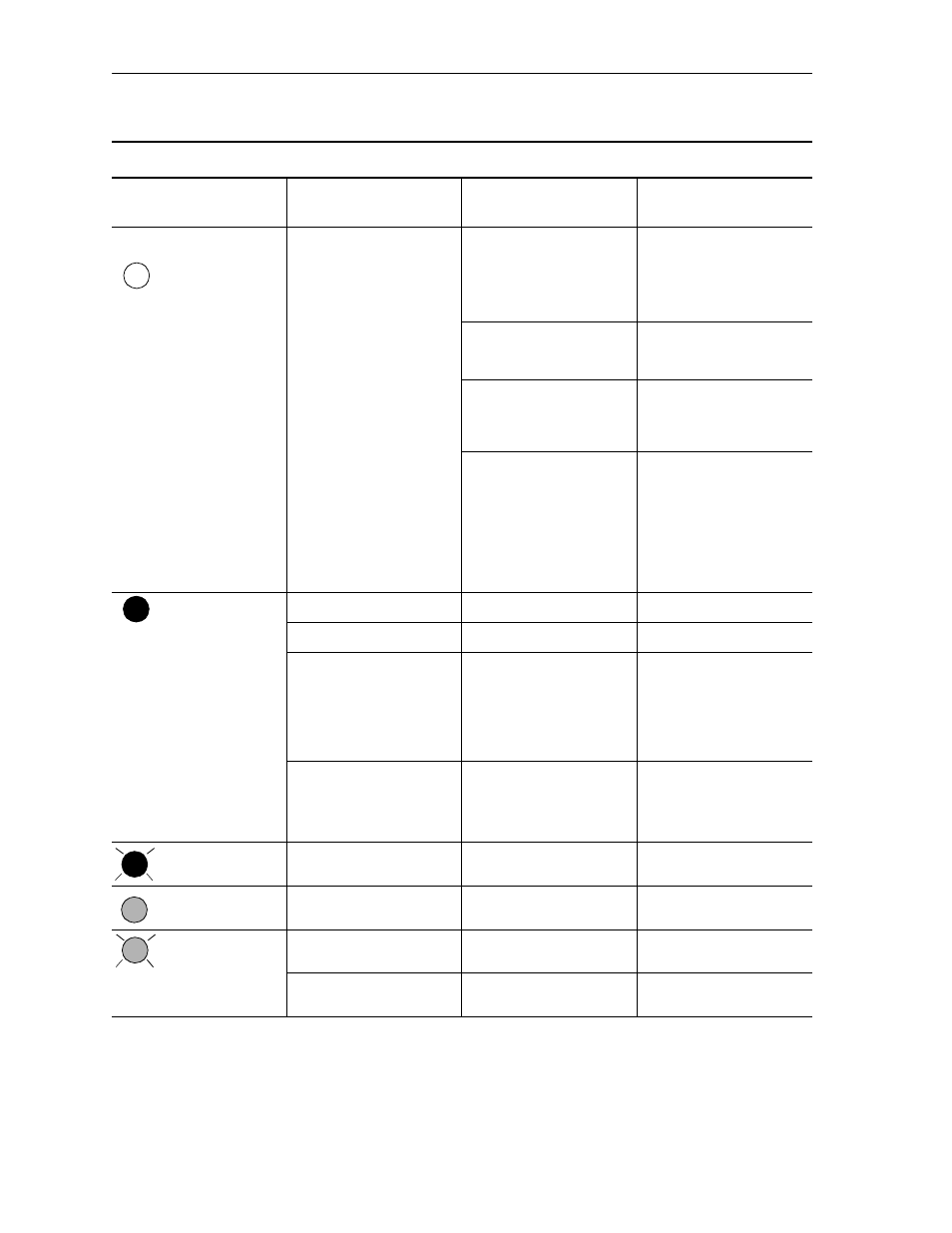
TROUBLESHOOTING CONSIDERATIONS
COMMUNICATIONS
INDICATOR
DESCRIPTION
PROBABLE CAUSES
RECOMMENDED ACTION
OFF
Module does not power up
Bad cable connection
1. Verify proper connections
on the module.
2. Verify proper connections
to processor or link coupler.
3. Replace 1747-C10 Cable.
Power supply overloaded
Evaluate chassis backplane
loading for proper sizing of
power supply.
No power to link coupler if on
DH485 network
If no processor is connected to
link coupler, provide 190mA or
24 VDC to screw terminals on
link coupler.
Defective chassis power
supply
1. Check for proper power
supply connections.
2. Check for proper power
suplly voltage.
3. Replace power supply.
4. Disconnect module. Call
your Allen-Bradley service
representative.
ILLUMINATED RED
During power up
Normal
None.
During self diagnostics
Normal
None.
Hardware malfunction
Defective power supply
1. Check for proper power
supply voltage.
2. Replace power supply.
3. Disconnect module. Call
your Allen-Bradley service
representative.
Software malfunction
Diagnostic failure
1. Consult error code on
module display.
2. Reset module.
3. Cycle power to module.
FLASHING RED
Illegal network connection
Improper module setup
configuration
Refer to module display.
ILLUMINATED GREEN
Communicating on network
Module configured for Monitor
mode
None.
FLASHING GREEN
Communicating on network
Module configured for Modify
mode
None.
Data being entered in Monitor
Override mode
None.