Application example 1, Application example 1 -12, Example 1 – Rockwell Automation 1747-DTAM-E,D17476.1 Data Table Access Module (DTAM) User Manual
Page 72: 12 message capability
8-12
Message Capability
Publication 1747-6.1
Application Example 1
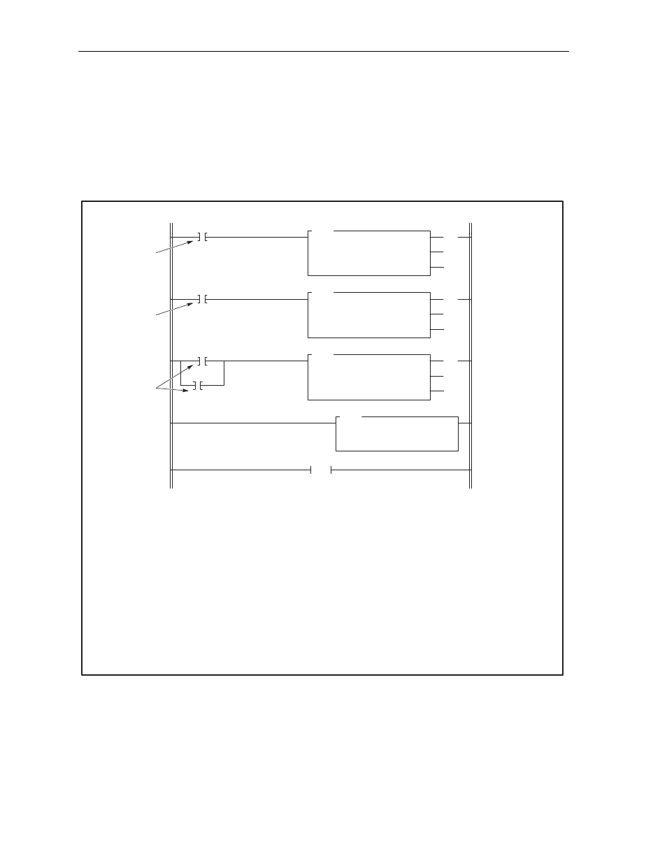
Application example 1 uses two 18-word message instructions to
enter variable data for high and low limits of a machine process. It
also uses an 8-word message instruction to prompt you if data is not
entered. The 5/02 ladder logic program is shown below. The data
monitor displays for the message instructions and the user-defined
data files are shown on the following page. The procedure to display
the message is shown on page 8-16.
Example 1
0
I:1.0
0
MSG
READ/WRITE
MESSAGE
Read/Write
Target Device
Control Block
Control Block Length
WRITE
485 CIF
N7:0
7
(EN)
(DN)
(ER)
1
17
(EN)
(DN)
(ER)
B3
MSG
READ/WRITE
MESSAGE
Read/Write
Target Device
Control Block
Control Block Length
WRITE
485 CIF
N7:30
7
2
18
(EN)
(DN)
(ER)
B3
MSG
READ/WRITE
MESSAGE
Read/Write
Target Device
Control Block
Control Block Length
WRITE
485 CIF
N7:60
7
3
CLR
CLEAR
Dest
B3:1
0000000000000
000
B3
20
4
END
18-word Write
Message instruction
for low level data
18-word Write
Message
instructions for high
level data
8-word Write
Message instruction
for no data entry
Reset Message
acknowledge bits
Message trigger
input
Acknowledge Bit
from message in
rung 0
No-acknowledge
bits from
messages in
rungs 0 and 1
Operation Notes
Rung 0
Input instruction I:1.0/0 initiates the first message instruction.
This message prompts you to enter a value for the low range
of the machine process. The initial value indicates that a
minimum value of one should be entered. The Data Entry
Destination Address is N10:1. The Acknowledge Bit Address
is B3:1.0/1 or B3/17.
Rung 1
This input instruction B3/17, is the user-designated
acknowledge bit from the first message instruction. It is used
to initiate the second message which prompts you to enter a
value for the high range of the machine process. The initial
value indicates a maximum of 250 should be entered. The
Data Entry Destination Address is N10:2. The Acknowledge
Bit Address is B3:1.0/3 or B3/19.
Rung 2
Input instructions B3/18 and B3/20 are the user-designated
no-acknowledge bits from the previous message
instructions. If the module [ESC] key is pressed before
entering either or both values, the message will prompt you
that no value has been entered.
Rung 3
This Clear instruction is enabled every scan to reset the
user-defined acknowledge and no-acknowledge bits to zero.
Rung 4
This is the end of the user program.