Dst and src – Rockwell Automation 1770, D17706.5.16 Ref Mnl DF1 Protocol Command User Manual
Page 83
6–4
Application Layer Message Packets
Publication 1770Ć6.5.16 - October 1996
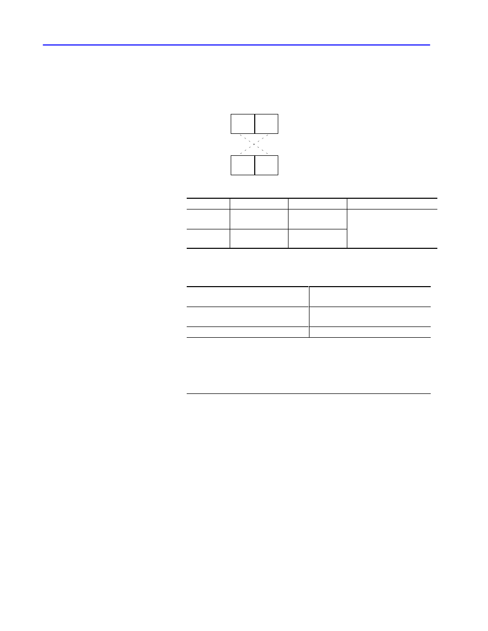
DST and SRC
Form the DST and SRC bytes of a reply message by interchanging
the DST and SRC bytes of the corresponding command message:
DST
SRC
SRC
DST
Command
Reply
Byte
Contents
Value supplied by Value range
DST
(destination)
receiving message application layer
•
0 to 376 (octal) for DF1
•
0 to 376 (octal) for DH
SRC
(source)
sending message
data link layer
•
0 to 376 (octal) for DH
•
0 to 77 (octal) for DH+
•
0 to 31 (decimal ) for DH485
When sending messages from asynchronous devices, special
consideration must be given to the SRC byte:
When sending a message from an
asynchronous device connected
Set the SRC byte
to the network
➀
= 0 (the module will set the byte to its own
node number)
directly to a 1771ĆKG
10 (octal)
➀
If you connect to channel 0 of a PLCĆ5/11, Ć5/20, Ć5/30, Ć5/40, Ć5/60 or Ć5/80 processor and you
send a PLCĆ2 unprotected write, protected write, protected bit write, or unprotected bit write, what
you put into the SRC byte is very important. This determines the compatibility file. This means
that the value of the SRC byte specifies the data table file number that is written to the PLCĆ5
processor. The source byte will not be overwritten by channel 0. For SLC 500 processors, the
compatibility file is always 9.