Protected bit write – Rockwell Automation 1770, D17706.5.16 Ref Mnl DF1 Protocol Command User Manual
Page 102
7–15
Communication Commands
Publication 1770Ć6.5.16 - October 1996
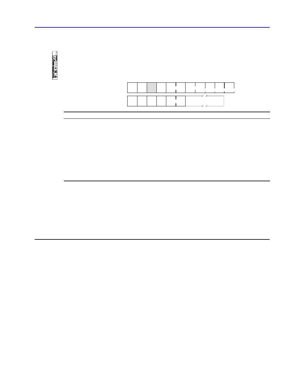
protected bit write
Sets or resets individual bits within limited areas of the PLC data
table memory. The access is limited by memory access rungs in the
communication zone of the PLC processor’s ladder diagram
program.
C
CMD
02 STS
TNS
ADDR
R
STS
TNS
CMD
42
DATA (max. 244 bytes)
SET RESET
Up to 60 masks of this form.
DST SRC
SRC DST
DATA
ADDR
SET
RESET
DATA is:
•
4Ćbyte blocks, each of
which contains a 16Ćbit
address field
•
Use ADDR to specify the
address of the byte to be
modified in the PLC data
table memory.
•
Use SET to specify which
bits to set to 1 in the
addressed PLC byte.
•
Use RESET to specify
which bits to reset to 0 in
the addressed PLC byte.
address field
•
a set mask
•
a reset mask
•
Put the low byte (least
significant bits) of the PLC
address value into the first
byte of the ADDR field.
•
A 1 in the SET bit position
means to set the
corresponding bit in the
addressed PLC byte to 1.
•
A 1 in a RESET bit position
means to reset the
corresponding bit in the
addressed PLC byte to 0.
y
•
A 0 in the SET bit position
means to leave the
corresponding bit in the
PLC byte unchanged.
•
A 0 in the RESET bit
position means to leave
the corresponding bit in the
PLC byte unchanged.
Important: For some PLC processors, the interface module at the
receiving PLC node executes this command by making
a copy of the addressed PLC byte. It then sets or resets
the appropriate bits and writes the byte back into PLC
memory. At the same time, the PLC processor can
change the states of the original bits in memory.
Because of this, some data bits may unintentionally get
overwritten.
•
1774ĆPLC
•
PLCĆ2
•
PLCĆ3
•
PLCĆ5
•
PLCĆ5/250