Rockwell Automation 1770, D17706.5.16 Ref Mnl DF1 Protocol Command User Manual
Page 221
13–6
PLC Addressing
Publication 1770Ć6.5.16 - October 1996
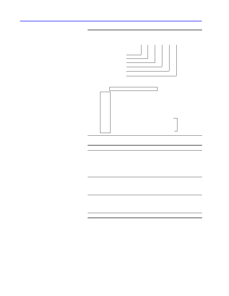
Example: PLCĆ3 logical binary addressing format
E3
1
8
260
0
Data table area = level 1
0
Context = level 2
Section = level 3
File = level 4
Structure = level 5
Word = level 6
level
Byte 1
Byte 2
Byte 3
Byte 4
6 5 4 3 2
1
Byte 5
Byte 6
1 0 1 1 0
0
0 0
flag byte: specifies that the default
values are used for levels 1, 2, and 5
0 0 1 0 0
0
0 0
level 3 (value = 8)
1 1 1 1 1
1
1 1
level 4 delimiter: used to signal that the
level 4 address uses the next two bytes
0 0 0 1 0
0
0 0
level 4 (low byte)
0 0 0 0 0
1
0 0
level 4 (high byte)
0 0 0 0 0
0
0 0
level 6 (value = 0)
= value
260 (decimal)
8 7
bit
5 4 3 2 1
0
7 6
Bytes
Description
1
Flag bits 0, 1, and 4 are set to 0 Ċ default values are used for levels 1,
2, and 5 of the PLCĆ3 address.
Flag bits 2, 3, and 5 are set to 1 Ċ you must specify a value for levels
3, 4, and 6 in the bytes following the flag byte. (Even though the value
of address level 6 is 0, the default value, the last level of a PLCĆ3
address is always specified in the ADDR message packet field.)
2
Address levels are specified lowest level to highest level. Address level
3 is the lowest level that must be specified, so it is specified in the first
byte following the flag byte. It is followed by address level 4, then
address level 6.
3, 4, and 5
The levelĆ4 address is 260 (decimal), which is too large to fit in one
byte. Therefore, byte 3 is a delimiter that contains all 1's (FF hex) and is
used to delimit the 2Ćbyte level 4 address value. The value 260 is then
coded low byte first in bytes 4 and 5.
6
Specifies the levelĆ6 address.