Full duplex protocol diagrams, Fullćduplex protocol diagrams, Normal message transfer – Rockwell Automation 1770, D17706.5.16 Ref Mnl DF1 Protocol Command User Manual
Page 64
4–10
Using Full-duplex Protocol to Send and Receive Messages
Publication 1770Ć6.5.16 - October 1996
These transfer diagrams show events that occur on various
interfaces. Time is represented as increasing from the top of the
diagram to the bottom. Link-layer data bytes are represented by
“xxxx” and corrupted data by “???”.
For this diagram
See page
normal message transfer
message transfer with NAK
message transfer with timeout & ENQ
message transfer with reĆtransmission
message transfer with message sink full
message transfer with NAK on reply
message transfer with timeout and ENQ for the reply
message transfer with message source full on the reply
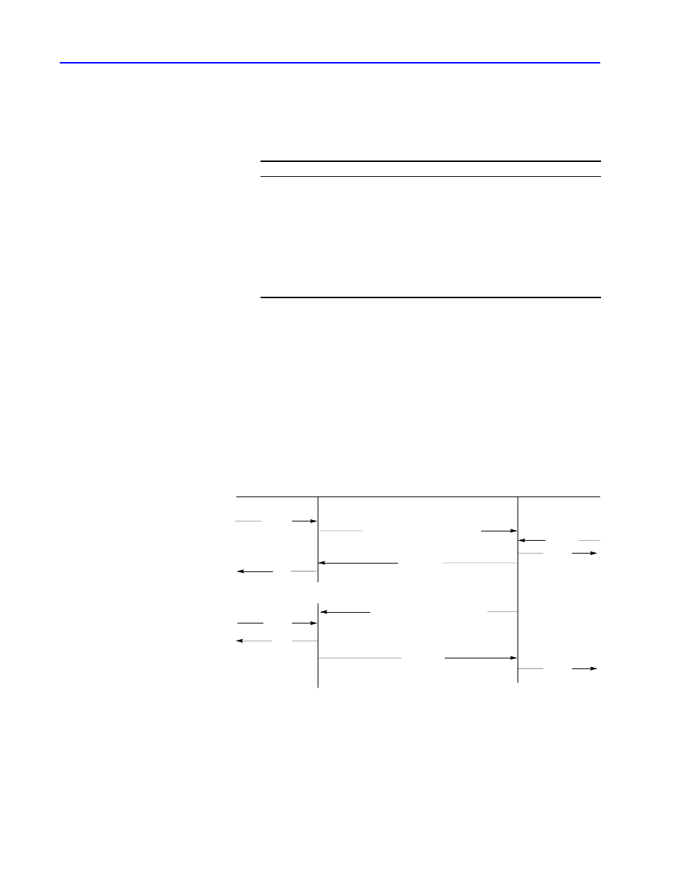
Normal Message Transfer
In this transfer:
•
t
he transmitter sends the data to the receiver
•
the sink sends a “not full” message
•
the receiver sends the data to the sink and sends a DLE ACK to
the transmitter
•
the transmitter tells the source that the data was delivered
•
reply is successfully returned
xxxx
not full
OK
OK
xxxx
not full
xxxx
DLE STX xxxx DLE ETX BCC/CRC
DLE ACK
DLE STX xxxx DLE ETX BCC/CRC
DLE ACK
Source
Transmitter
Link
Receiver
Sink
command
reply
(sometime later ...)
FullĆduplex Protocol
Diagrams