Plcć3 logical addressing – Rockwell Automation 1770, D17706.5.16 Ref Mnl DF1 Protocol Command User Manual
Page 220
13–5
PLC Addressing
Publication 1770Ć6.5.16 - October 1996
PLCĆ3 Logical Addressing
PLC-3 processors use a form of logical addressing known as
extended addressing. With extended addressing, you specify the
address for each level (or sub-division) of PLC-3 memory, down to
the smallest subdivision you want to access.
You can use this method to specify up to 6 levels of extended
addressing, which is enough to address any particular word in PLC-3
memory. (For more information on PLC-3 extended addressing,
refer to your PLC-3 Family Programming and Operations Manual.)
To send a PLC-3 command message to a PLC-3 node, put the
extended address of the node in the PLC-3 LOGICAL ADDR field.
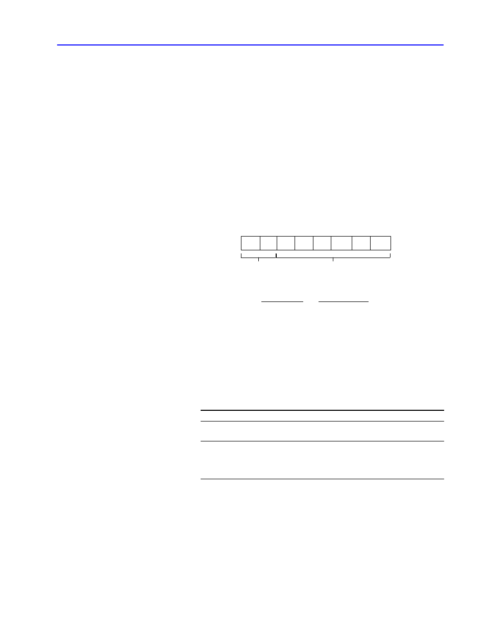
The first byte in the PLC-3 address field is a flag byte.
1
1
0
1
1
0
0
1
7
6
5
4
3
2
1
0
Flag byte
associated with levels 1 - 6 of a
PLCĆ3 extended address
always set to zero
If a bit is set to 0:
This address level
Has this default value
1
3 (data table)
2
1 (current context)
all others
0
If a bit is set to 1, you must specify a value for the corresponding address
level.
Important: You must specify the last level of a PLC-3 address
in the address field even though it is equal to the
default value.
If
Then
the address values can be specified in one
byte each
you can code the values directly
it takes two bytes to specify an address
you must use a delimiter byte of value FF
(hex) before each twoĆbyte address. Any
twoĆbyte value must be encoded low byte
first.
The following example shows how to enter a PLC-3 extended
address in logical binary format in the address message packet field.