Plcć3 physical addressing – Rockwell Automation 1770, D17706.5.16 Ref Mnl DF1 Protocol Command User Manual
Page 222
13–7
PLC Addressing
Publication 1770Ć6.5.16 - October 1996
PLCĆ3 Physical Addressing
PLC-3 processors use physical addresses that are related to logical
addresses by means of pointers. Since no two PLC-3 systems are
configured identically, the pointers are not fixed. Therefore, there is
no algorithm for converting logical to physical PLC-3 addresses.
A PLC-3 physical address goes in the 4-byte field labeled PLC-3
PHYSICAL ADDR in the PLC-3 physical reads or physical writes.
(See Chapter 7, “Communication Commands.”)
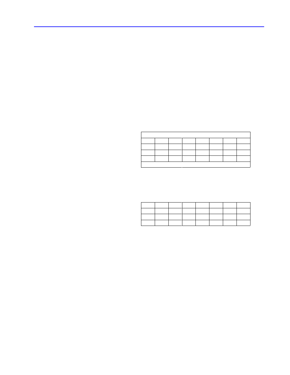
A physical address is made of 24 bits. These bits are inserted in the
message packet physical address field as follows. (Bits are labelled
A1 to A24 respectively.)
Function (FNC) Field
First byte
A24
A23
A22
A21
A20
A19
A18
A17
Second byte
0
0
0
0
0
0
0
0
Third byte
A8
A7
A6
A5
A4
A3
A2
A1
Fourth byte
A16
A15
A14
A13
A12
A11
A10
A9
Size Field
For example, to address a command message to physical word
address 12,200 decimal (002FA8 hex), you use the following binary
code in the address field:
First byte
0
0
0
0
0
0
0
0
(value 00 hex)
Second byte
0
0
0
0
0
0
0
0
(always 00 hex)
Third byte
1
0
1
0
1
0
0
0
(values A8 hex)
Fourth byte
0
0
1
0
1
1
1
1
(value 2F hex)
The recommended procedure for uploading or downloading PLC-3
memory is to begin at physical address 0000 and proceed
sequentially to the end of memory. Therefore, each successive
physical read or write begins at the next physical address after the
one where the previous command stopped. Since a single physical
read or write command can transfer only about 120 words of data,
it takes many such commands to upload or download the entire
PLC-3 memory.