Protected write, Read bytes physical (physical read), Read diagnostic counters – Rockwell Automation 1770, D17706.5.16 Ref Mnl DF1 Protocol Command User Manual
Page 106
7–19
Communication Commands
Publication 1770Ć6.5.16 - October 1996
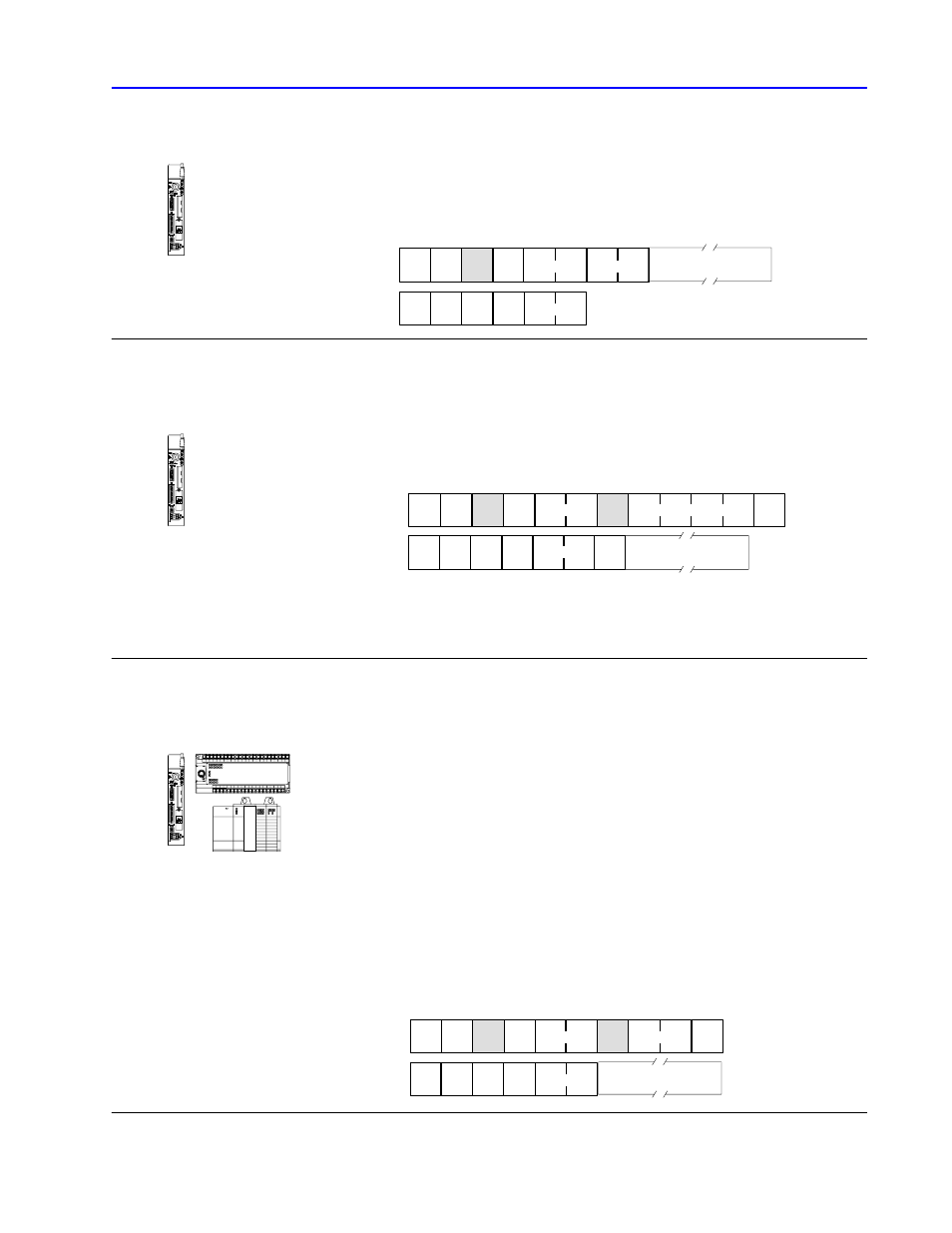
protected write
Writes words of data into limited areas of the PLC data table
memory. Its access is limited by memory access rungs in the
communication zone of the processor’s ladder diagram program.
C
CMD
00 STS
TNS
ADDR
R
STS
TNS
CMD
40
Data (max. 244 bytes)
DST SRC
SRC DST
read bytes physical (physical read)
Performs an upload after receiving a reply that an upload (download)
all request has been successfully performed.
CMD
0F
STS
FNC
17
TNS
C
CMD
4F STS
TNS
R
TNS
DST SRC
SRC DST
A
PLCĆ5 phys. address
Size
Data (up to 240 bytes)
A - extended status byte if there is an error. Otherwise, it will be data at physical address,
first word, low byte.
Size - the number of bytes to read, up to 240 (must be an even number).
read diagnostic counters
Reads up to 244 bytes of data from the PROM or RAM of an
interface module. Use this command to read a module’s diagnostic
timers and counters.
You must use diagnostic status to obtain the starting address of the
diagnostic counters, except for the PLC-5, PLC-5/250, and SLC 500
processors. PLC-5 and PLC-5/250 processors don’t require that this
address be specified, though you must include a dummy value in the
ADDR field, which the PLC-5 or PLC-5/250 processor ignores.
For SLC 500 processors, zero is the only valid value for the ADDR
field. (For listings of read diagnostic counters status information,
see Chapter 10, “Diagnostic Status Information.”)
C
CMD
06
STS
FNC
01
TNS
ADDR
SIZE
R
STS
TNS
CMD
46
Data (max. 244 bytes)
DST SRC
SRC DST
•
1774ĆPLC
•
PLCĆ2
•
PLCĆ3
•
PLCĆ5
•
PLCĆ5/250
•
PLCĆ5
•
PLCĆ5/250
(receive only)
•
PLCĆ5/VME
•
1774ĆPLC
•
MicroLogix 1000
•
PLCĆ2
•
PLCĆ3
•
PLCĆ5
•
PLCĆ5/250
(receive only)
•
SLC 500
•
SLC 5/03
•
SLC 5/04