Figure 4.12 response frame – Rockwell Automation 900 Temperature Controller Communications Functions - Series B User Manual
Page 70
Publication 900-UM004D-EN-E - July 2010
4-12
Modbus Communications Procedure
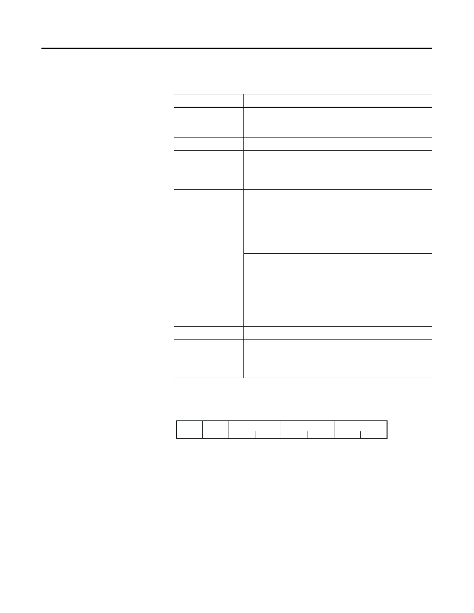
Figure 4.12 Response Frame
Table 4.9
Name
Description
Slave address
Specify the 900-TC8, 900-TC16, or 900-TC32’s unit number.
The unit number can be set between H’01 and H’63 hexadecimal
(1…99 decimal).
Function code
The Write Variable Area function’s function code is H’10.
Write start address
Specify the starting address where the setting data will be
written.
Refer to Chapter 5 Communications Data for Modbus for details
on addresses.
Number of elements
Specify 2 times the number of setting data items as the number
of elements to be written.
The setting range for the number of elements is H’0002…H’0068
(2…104).
When H'0068 is set, 52 items of setting data can be read.
Example: When writing 2 items of setting data, set the number of
elements to H’0004.
2-byte Mode
Specify the number of setting data items to be written as the
number of elements.
The setting range for the number of elements is H'0001…H'0068
(1…104).
When H'0068 is set, 104 items of setting data can be read.
Example: When reading two items of setting data, set the
number of elements to H'0002.
Byte count
Specify the number of bytes of write data.
CRC-16
This check code is calculated with the data from the slave
address to the end of the data.
For details on the CRC-16 calculation, refer to CRC-16 Calculation
Example in on page 5-2.
CRC-16
1
1
2
2
H'10
Number of
Elements
2 bytes
Slave
address
Function
code
Write
start address