Interface -3 wiring -3, Rs-485 -3, Interface – Rockwell Automation 900 Temperature Controller Communications Functions - Series B User Manual
Page 11: Wiring, Rs-485
Publication 900-UM004D-EN-E - July 2010
About Communications Methods
1-3
Interface
Communications with the host device are carried out through a standard
RS-485 or RS-232C(900-TC8x) interface. Use a cat. no. 900-CONVxx
interface converter for RS232C/USB to RS485 conversion.
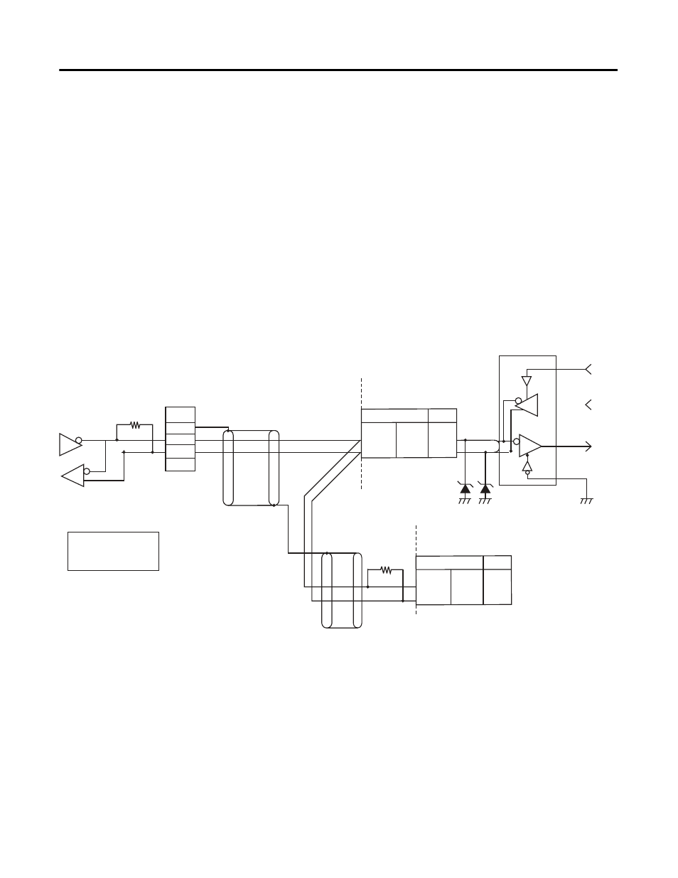
Wiring
RS-485
•
RS-485 connections can be 1:1 or 1: N. A maximum of 32 Units
(including the host device) can be connected in one-to-N systems.
•
The total cable length is 500 m max.
•
Use a shielded, twisted-pair cable #24 AWG (0.205 mm
2
)…#14 AWG
(2.081 mm
2
) for the 900-TC8 and 900-TC16.
•
Use a shielded, AWG24 to AWG18 (cross-sectional area of 0.205 to
0.823 mm2) twisted-pair cable for the 900-TC32.
Match the communications specifications of the 900-TCx and the host device.
If a one-to-N system is being used, be sure that the communications
specifications (Refer to Communications Specifications on page 1-2) of all devices
in the system (except individual unit numbers) are the same.
This section explains how to set the 900-TCx's communications specifications.
For details on the host device, refer to publication 900-UM007*.
SG
FG
Abbr
_
+
900-TC32
12
11
8
7
Pin No.
RS-485
RX
TX
Communications Transceiver
6.8V
Terminator
120
Ω
(1/2W)
900-TCx
end node
RS-485
Use a terminator of resistance
120
Ω
= (1/2W)
Shielded cable
Both ends of the transmission line
(including the host device) must be
specified (by setting terminator ON) as
the end node. The total resistance of
the terminators must be at least 54
Ω
.
A
Shielded cable
Host Device
RS-485
900-TC8/16
Abbr
A ( – )
B ( + )
900-TC32
12
11
8
7
Pin No.
900-TC8/16
Abbr
A ( – )
B ( + )