Rockwell Automation 900 Temperature Controller Communications Functions - Series B User Manual
Page 53
Publication 900-UM004D-EN-E - July 2010
Communications Data
3-11
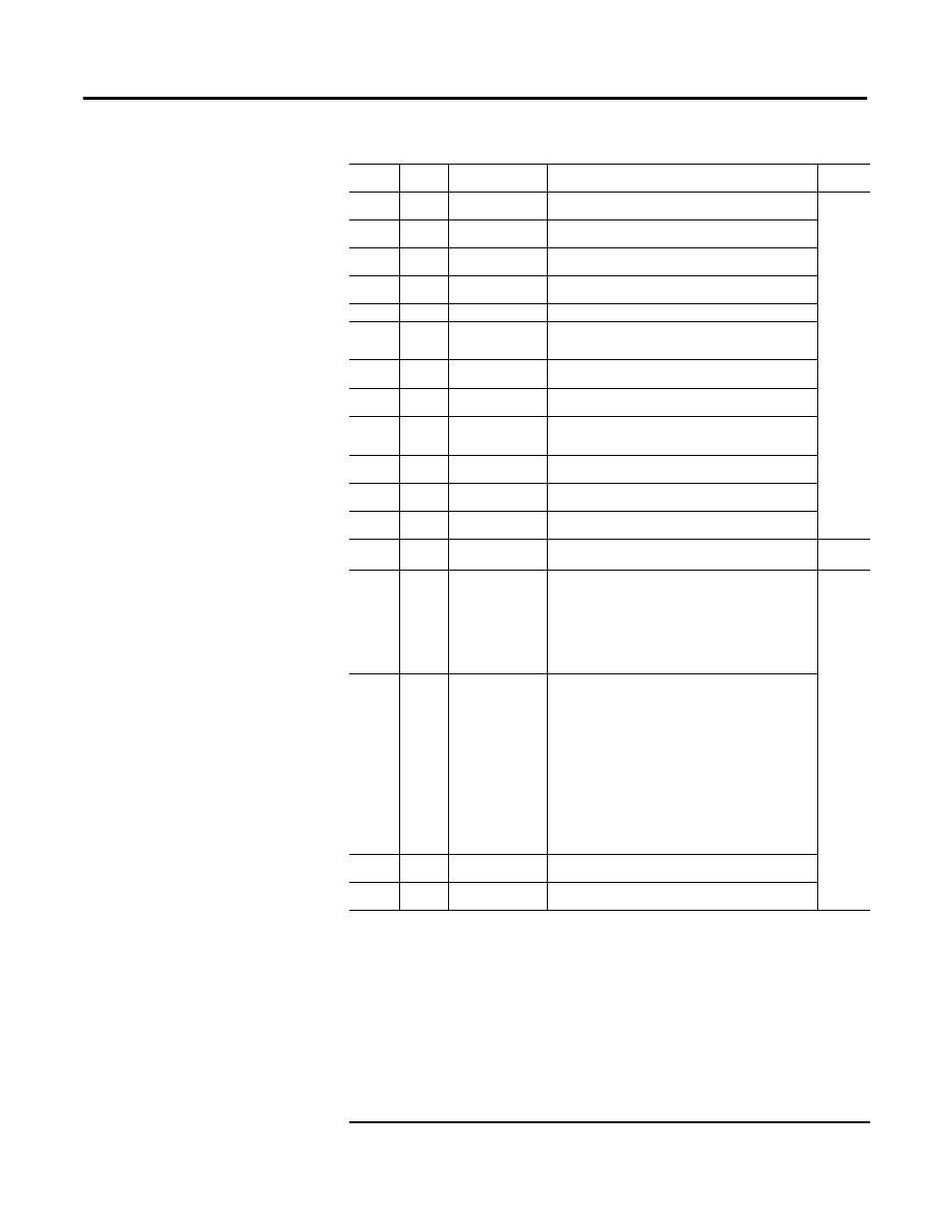
C3 (83)
0054
Soak time unit
H’00000000 (0): Minutes
H’00000001 (1): Hours
Advanced
function
setting
C3 (83)
0055
Alarm SP selection
H’00000000 (0): Set point during SP ramp
H’00000001 (1): Set point
C3 (83)
0056
Auxiliary Output 3
assignment
H’00000000…H’0000000F (0…15)
* Same settings as Auxiliary Output 1 assignments
C3 (83)
005B
Manual MV limit
enable
H’00000000 (0): OFF
H’00000001 (1): ON
C3 (83)
005D
AT calculated gain
H’00000001...H’00000064 (0.1...10.0)
C3 (83)
005E
AT Hysteresis
H’00000001...0000270F (0.1...999.9: Controllers with TC/Pt
universal input)
(0.01...9.99: Controllers with analog input)
C3 (83)
005F
Limit Cycle MV
amplitude
H’00000032...H’000001F4 (5.0...50.0)
C3 (83)
0067
PV Rate of change
calculation period
H’00000001...H’000003E7 (1...999)
C3 (83)
0068
Automatic Cooling
coefficient
adjustment
H’00000000 (0): OFF
H’00000001 (1): ON
C3 (83)
0069
Heater Overcurrent
use
H’00000000 (0): OFF
H’00000001 (1): ON
C3 (83)
006A
Heater Overcurrent
latch
H’00000000 (0): OFF
H’00000001 (1): ON
C3 (83)
006B
Heater Overcurrent
Hysteresis
H’00000001...H’000001F4 (0.1...50.0)
C3 (83)
006C
Extraction of square
root enable
H’00000000 (0): OFF
H’00000001 (1): ON
Initial set-
ting
C3 (83)
006D
PF Setting
H’00000000 (0): Not assigned.
H’00000001 (1): Run
H’00000002 (2): Stop
H’00000003 (3): RUN/STOP
H’00000004 (4): 100% AT execute
H’00000005 (5): 40% AT execute
H’00000006 (6): Alarm latch cancel
H’00000007 (7): Auto/manual switch
H’00000008 (8): Monitor/setting item
Advanced
function
setting
C3 (83)
006E
Monitor/Setting Item
1
H’00000000 (0): Disabled
H’00000001 (1): PV/SP/Multi-SP
H’00000002 (2): PV/SP/MV
H’00000003 (3): PV/SP/soak time remain
H’00000004 (4): Proportional band (P)
H’00000005 (5): Integral time (I)
H’00000006 (6): Derivative time (D)
H’00000007 (7): Alarm value 1
H’00000008 (8): Alarm value upper limit 1
H’00000009 (9): Alarm value lower limit 1
H’0000000A (10): Alarm value 2
H’0000000B (11): Alarm value upper limit 2
H’0000000C (12): Alarm value lower limit 2
H’0000000D (13): Alarm value 3
H’0000000E (14): Alarm value upper limit 3
H’0000000F (15): Alarm value lower limit 3
C3 (83)
006F
Monitor/Setting Item
2
H’00000000...H’0000000F (0 ...5)
* Same as for Monitor/Setting Item 1.
C3 (83)
0070
Monitor/Setting Item
3
H’00000000...H’0000000F (0 ...5)
* Same as for Monitor/Setting Item 1.
Table 3.3 Variable Type C3 (83)
Variable
Type
Address
Item (Parameter)
Set (Monitor) Value
Function
Group
➊
The input type can be selected to march the connected sensor. There are two input types specifications:
Thermocouple/Resistance thermometer input and Analog input.
➋
The parameter will not be shown on the Controller display when alarm 3 is not assigned to an output.
➌
Communications parameters are enabled after they have been changed by resetting the controller.
➍
For controllers with two event inputs (events 1 and 2), this cannot be set if the number of Multi-SP uses parameter is set to 1
or 2
➎
For controllers with two event inputs (events 1 and 2), this cannot be set if the number of Multi-SP uses parameter is set to 2.
➏
PRST (program start) can be set even when the program pattern is set to OFF, but the function will be disabled.
➐
The logic of CompoWay/F (900-TC) operation command code 00 (communications writing) is not affected.
➑
The setting (monitor) range depends on the transfer output type setting. (See the setting data list for details.)
➒
P.END (program end output) can be set even when the program pattern is set to OFF, but the
function will be disabled.
➓
The output turns ON when the status of either the Control Output 1 ON/OFF Count Alarm or the Control Output 2 ON/OFF
Count Alarm turns ON.