Partial exception to modbus address correspondence, Set values, Number of elements -7 – Rockwell Automation 900 Temperature Controller Communications Functions - Series B User Manual
Page 65: Number of elements
Publication 900-UM004D-EN-E - July 2010
Modbus Communications Procedure
4-7
Modbus Addresses Corresponding to 900-TC (CompoWay/F)
Setup Areas 0 and 1
Setup Area 0 and Setup Area 1 do not correspond directly to Modbus
addresses, but the following areas have a rough correspondence with one
exception.
Partial Exception to Modbus Address Correspondence
The Hysteresis (Heating), Hysteresis (Cooling), Control Period (Heat), and
Control Period (Cool) parameters are assigned to consecutive addresses, but
the Control Period parameters are Setup Area 1 parameters. For this reason, an
operation error will occur when writing the Control Period (Heating or
Cooling) from the Setup Area 0 side, e.g., from the Operation function group.
Number of Elements
The number of elements is expressed in 2-byte hexadecimal. The setting range
for the number of elements varies according to the command.
For example, when the number of elements is “0010,” this specifies eight items
of data (H’10) from the address.
• Four-byte Mode
One element uses 2 bytes of data, so specify two-element units. Reading
and writing in 4-byte units is executed by specifying an even address and
specifying the number of elements in multiples of 2.
• Two-byte Mode
One element uses 2 bytes of data, so specify one-element units. Reading
and writing in 2-byte data units is executed by specifying 1-element
units.
Set Values
The values read from the variable area or written to the variable area are
expressed in hexadecimal, ignoring the decimal point position. (Negative
values are expressed in 2’s complement format.)
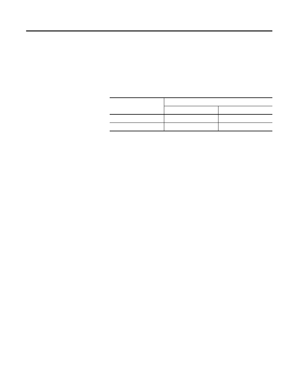
Table 4.5
Setup Area
Modbus Addresses
Area Number
Address Range
Setup area 0
00…0B, 20…2B
0000…0BFE, 2000…2B7F
Setup area 1
0C…1F, 13…33
0C00…1366, 2C00…3333