Rockwell Automation 900 Temperature Controller Communications Functions - Series B User Manual
Page 50
Publication 900-UM004D-EN-E - July 2010
3-8
Communications Data
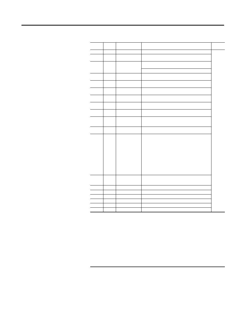
C3 (83)
002B
Input digital filter
H’00000000…0000270F (0.0…999.9)
Advanced
Setting
Function
Group
C3 (83)
002C
Additional PV display
H’00000000(0)
OFF
H’00000001(1)
ON
C3 (83)
002D
MV display
H’00000000(0)
OFF (display of manipulated variable
OFF)
H’00000001(1)
ON (display of manipulated variable ON)
C3 (83)
002E
Automatic return of
display mode
H’00000000(0)
OFF
H’00000001…H’00000063 (1…99)
C3 (83)
002F
Alarm 1 latch
H’00000000(0)
OFF
H’00000001(1)
ON
C3 (83)
0030
Alarm 2 latch
H’00000000(0)
OFF
H’00000001(1)
ON
C3 (83)
0031
Alarm 3 latch➋
H’00000000(0)
OFF
H’00000001(1)
ON
C3 (83)
0032
Protect function
group move time
H’00000001…H’0000001E (1…30)
C3 (83)
0033
Input error output
H’00000000(0)
OFF
H’00000001(1)
ON
C3 (83)
0034
Cold junction
compensation
method
H’00000000(0)
OFF
H’00000001(1)
ON
C3 (83)
0035
MB command logic
switching ➐
H’00000000(0)
OFF
H’00000001(1)
ON
C3 (83)
0036
PV color change
H’00000000(0)
ORG - Orange
H’00000001(1)
RED - Red
H’00000002(2)
GRN - Green
H’00000003(3)
Red to Green: When ALM 1 is ON
H’00000004(4)
Green to Red: When ALM 1 is ON
H’00000005(5)
Red to Green to Red: Within PV stable
band: Green. Outside stable
band: Red
H’00000006(6)
Green to Orange to Red: Within PV
stable band: Orange. Outside
stable band: Green, Red
H’00000007(7)
Orange to Green to Red: Within PV
stable band: Green. Outside
stable band: Orange, Red
C3 (83)
0037
PV stable band 2
H’00000001…0000270F
(0.1…999.9 for TC/Pt multi-input models)
(0.01…99.99 for Analog input models)
C3 (83)
0038
Alarm 1 ON delay
H’00000000…H’000003E7 (0…999)
C3 (83)
0039
Alarm 2 ON delay
H’00000000…H’000003E7 (0…999)
C3 (83)
003A
Alarm 3 ON delay➋ H’00000000…H’000003E7
(0…999)
C3 (83)
003B
Alarm 1 OFF delay
H’00000000…H’000003E7 (0…999)
C3 (83)
003C
Alarm 2 OFF delay
H’00000000…H’000003E7 (0…999)
C3 (83)
003D
Alarm 3 OFF delay➋ H’00000000…H’000003E7
(0…999)
Table 3.3 Variable Type C3 (83)
Variable
Type
Address
Item (Parameter)
Set (Monitor) Value
Function
Group
➊
The input type can be selected to march the connected sensor. There are two input types specifications:
Thermocouple/Resistance thermometer input and Analog input.
➋
The parameter will not be shown on the Controller display when alarm 3 is not assigned to an output.
➌
Communications parameters are enabled after they have been changed by resetting the controller.
➍
For controllers with two event inputs (events 1 and 2), this cannot be set if the number of Multi-SP uses parameter is set to 1
or 2
➎
For controllers with two event inputs (events 1 and 2), this cannot be set if the number of Multi-SP uses parameter is set to 2.
➏
PRST (program start) can be set even when the program pattern is set to OFF, but the function will be disabled.
➐
The logic of CompoWay/F (900-TC) operation command code 00 (communications writing) is not affected.
➑
The setting (monitor) range depends on the transfer output type setting. (See the setting data list for details.)
➒
P.END (program end output) can be set even when the program pattern is set to OFF, but the
function will be disabled.
➓
The output turns ON when the status of either the Control Output 1 ON/OFF Count Alarm or the Control Output 2 ON/OFF
Count Alarm turns ON.