Figure 4.8 response frame – Rockwell Automation 900 Temperature Controller Communications Functions - Series B User Manual
Page 68
Publication 900-UM004D-EN-E - July 2010
4-10
Modbus Communications Procedure
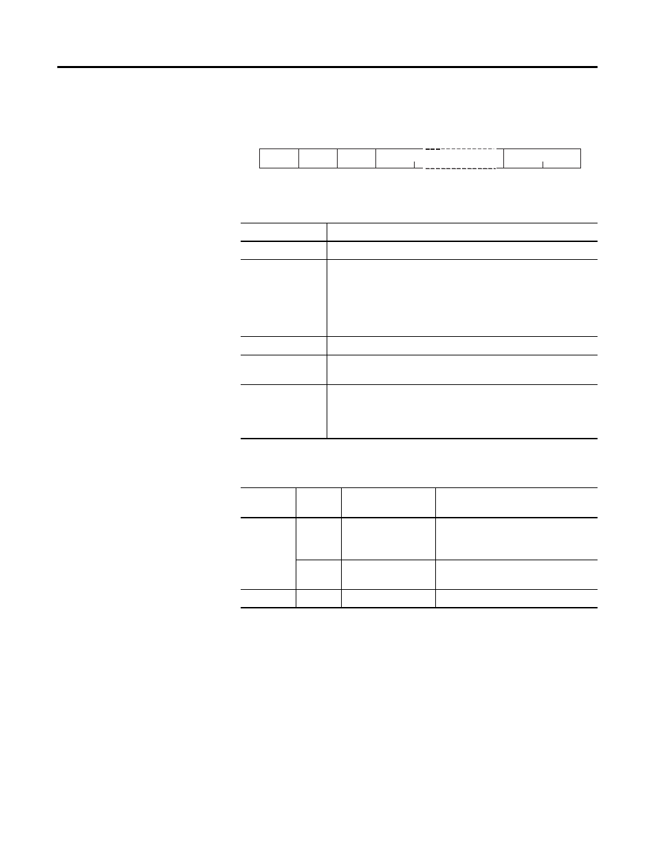
Figure 4.8 Response Frame
Table 4.7
Name
Description
Slave address
The value from the command frame is entered as-is.
Function code
This is the received function code.
When the function ended normally, the function code is left as-is.
When an error occurred, the hexadecimal value of H’80 is added to
the function code to indicate that the response is an error response.
Example: Received function code = H’03
Function code in response frame when an error occurred = H’83
Byte count
Contains the number of bytes of read data.
Number of
elements
Contains the number of setting data items that were read.
CRC-16
This check code is calculated with the data from the slave address
to the end of the data.
For details on the CRC-16 calculation, refer to CRC-16 Calculation
Example on Page 4-2.
Table 4.8 Response Code
Function
Code
Error
Code
Error Name
Cause
H’83
H’02
Variable address error The read start variable address is
incorrect.
The variable area number is incorrect.
H’03
Variable data error
The number of elements exceeds the
allowed range.
H’03
—
Normal completion
No errors were found.
Slave
address
Function
code
Byte
count
1
1
1
2
CRC-16
0 to 212 (2
×
106)
Read data (for the
number of elements)
H'03