Inputs and outputs, Analog inputs, Combination generator control module – Rockwell Automation 1407-CGCM Combination Generator Control Module User Manual
Page 38: Generator voltage sensing inputs, Figure 28 - front panel layout
38
Rockwell Automation Publication 1407-UM001G-EN-P - April 2013
Chapter 3
CGCM Unit Operation
Inputs and Outputs
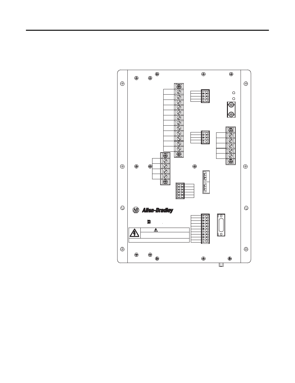
The figure below shows the front panel layout of the CGCM unit. Input and
output connections are made through the terminal blocks TB1…TB7.
Figure 28 - Front Panel Layout
Analog Inputs
The CGCM unit provides a number of analog inputs for use in the regulation
and control of stand-alone and paralleled generator systems. Each of the inputs is
outlined below.
Generator Voltage Sensing Inputs
The CGCM unit senses generator voltage through voltage transformers (VTs)
installed across the generator output leads.
CNA
CNB
Manufactured by
Basler Electric
R
BAT (-)
BAT (+)
DANGER
4
5
ID (+) 1A
ID (+) 5A
ID (-)
I3 (+) 1A
I3 (+) 5A
I3 (-)
I2 (+) 1A
I2 (+) 5A
I2 (-)
I1 (+) 1A
I1 (+) 5A
I1 (-)
TB5
TB6
TB3
SHLD 2
SHLD 2
EXC (+)
EXC (-)
TB2
Combination
Generator
Control Module
TB4
FLT
RD RLY
CH GND
TB7
ControlNet
Address
TB1
PMG A
PMG B
PMG C
SHLD 1
SHLD 1
V Bus A
V Bus B
V Bus C
V Bus N
V Gen A
V Gen B
V Gen C
V Gen N
VREF (+)
VREF (-)
SHLD 3
SHLD 3
A-COM
EX-D (+)
EX-D (-)
LS (+)
LS (-)
SHLD 4
Factory
Test
Port
HAZARDOUS VOLTAGE CAN CAUSE SHOCK, BURNS, OR DEATH.
1) DISCONNECT AND LOCK OUT ALL POWER SOURCES AND,
2) SHORT ALL CURRENT TRANSFORMER SECONDARIES BEFORE SERVICING.
MORE THAN ONE LIVE CIRCUIT. SEE DIAGRAM.
ADVERTISSMENT: CET EQUIPEMENT RENFERME PLUSIEURS CIRCUITS SOUS TENSION, VOIR LE SCHEMA