Metering – Rockwell Automation 1407-CGCM Combination Generator Control Module User Manual
Page 160
160
Rockwell Automation Publication 1407-UM001G-EN-P - April 2013
Chapter 7
Troubleshooting
Metering
If there is a difference between the metering data reported by the CGCM
unit and a reference meter, verify the metering used to determine CGCM
unit malfunction is being correctly used and in calibration.
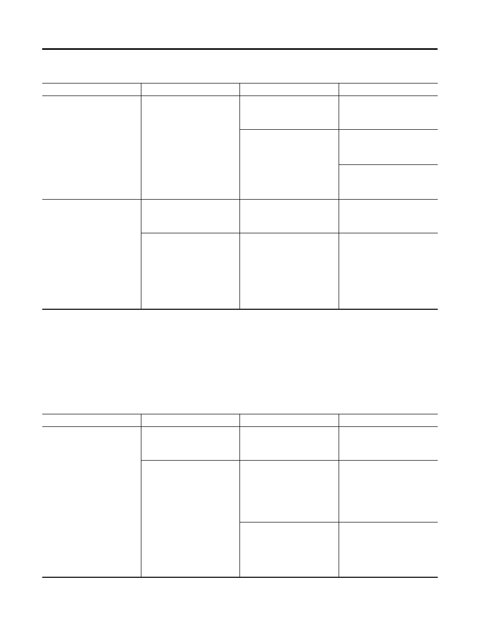
No close indication from CGCM unit
(cont.)
Voltage not matched
Observe voltage match tag during
synchronization
If voltage match indicated, check
close command tag. If no voltage
match indicated, check voltage
match error
Observe voltage error, generator
voltage, and selected bus voltage
reported by CGCM unit during
synchronization
If no voltage error is reported by
CGCM unit correct wiring and verify
appropriate Synchronization mode is
active
If voltage error is reported, verify
voltage setpoint to CGCM unit is
being adjusted appropriately to
provide voltage correction
Close indication from CGCM unit
when sync parameters not met
Configuration errors
Observe VT and Bus offset
configuration parameters to verify
they reflect the desired/expected VT
wiring
Correct configuration to match
expected VT wiring
Wiring errors
Adjust manually such that test
equipment (reference) indicates
synchronism, the observe
diagnostics above. This information
can be used to determine most
likely wiring error. Voltage not
matched, verify PT wiring and VT
ratios are correct. Phase or
frequency not matched; verify phase
rotation and polarity of VT wiring
Correct VT wiring
Table 29 - Synchronizing
Symptom
Most Likely Cause
Diagnostic Action
Corrective Action
Table 30 - Metering
Symptom
Most Likely Cause
Diagnostic Action
Corrective Action
Voltage does not read correctly
Configuration errors
Observe VT configuration and
rotation parameters and to verify
they reflect desired/expected VT
wiring
Correct configuration to match
expected VT wiring
Wiring errors
Observe each LL, phase, average
voltage, and rotation indication.
Indicated rotation matches
configured rotation. LL voltage (and
LN if applicable) indicated if all low
or high indicate ratio error, if one or
two are low or high indicate
polarity, grounding, or disconnection
Correct phase rotation, polarity,
grounding, or fusing as applicable
Measure signal at CGCM unit
terminals
If voltage indicated corresponds to
measured value, correct VT wiring.
If voltage indicated does not
correspond to measured voltage,
see configuration errors. If
configuration is correct, replace
CGCM unit