Step 5: start-up checklist, Prepare for drive startup – Rockwell Automation 20A PowerFlex 70 Adjustable Frequency AC Drive User Manual
Page 41
Rockwell Automation Publication 20A-IN009D-EN-P - June 2013
41
PowerFlex 70 Adjustable Frequency AC Drive
Table 20 - Encoder Specifications
Step 5: Start-up Checklist
• This checklist supports the basic start-up menu option. See
for information on other start-up routines.
• A HIM is required to run the basic start-up routine.
• The basic start-up routine can modify parameter values for analog and
digital I/O. Refer to
Common I/O Programming Changes on page 48
.
Prepare For Drive Startup
1. Verify the input supply voltage.
2. Check the output wiring.
3. Check the control wiring.
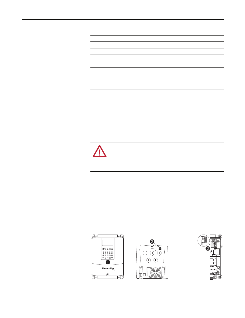
4. Connect a HIM to DPI Port 1 or 2.
Figure 14 - DPI Ports 1 and 2
Topic
Description
Type
Incremental, dual-channel
Supply
5V/12V Configurable ±5%
Quadrature
90° ±27°
Duty Cycle
50% +10%
Requirements
Encoders must be line driver type, quadrature (dual channel) or pulse (single channel), single-
ended or differential and capable of supplying a minimum of 10 mA per channel. The encoder
interface board accepts 5V or 12V DC square-wave with a minimum high state voltage of 3.5V
DC (5V mode) and 7.0V DC (12V mode). Maximum low state voltage is 1V DC (for both 5V and
12V modes). Maximum input frequency is 250 kHz.
ATTENTION: Power must be applied to the drive to perform the following
start-up procedure. Some of the voltages present are at incoming line potential.
To avoid electric shock hazard or damage to equipment, only qualified service
personnel can perform the following procedure. Thoroughly read and
understand the procedure before beginning.
CTRL BD
GND
Optional Service
Connection Board
(SK-M9-SCB1)
provides temporary
DPI connection with
drive cover removed.