Encoder interface option (only enhanced control) – Rockwell Automation 20A PowerFlex 70 Adjustable Frequency AC Drive User Manual
Page 40
40
Rockwell Automation Publication 20A-IN009D-EN-P - June 2013
PowerFlex 70 Adjustable Frequency AC Drive
For detailed information on installing and wiring a safety relay system, refer to
the DriveGuard Safe Torque Off Option (Series B) for PowerFlex 40P and
PowerFlex 70 AC Drives User Manual, publicatio
.
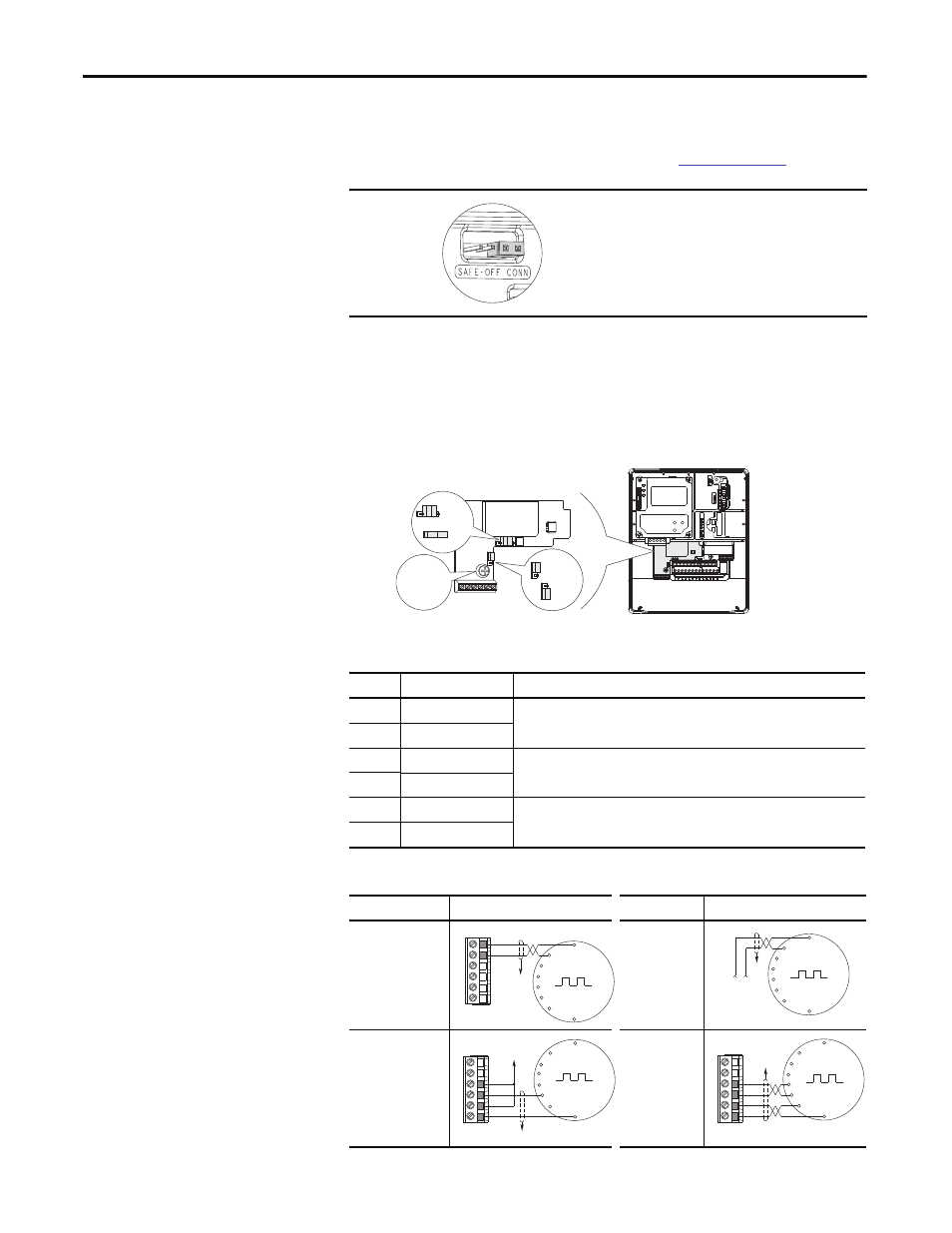
Encoder Interface Option (only enhanced control)
The optional PowerFlex encoder interface can source 5- or 12-volt power and
accept 5- or 12-volt single-ended differential inputs. The factory default setting is
12 volts.
Table 19 - Terminal Description
Figure 13 - Sample Encoder Wiring
IMPORTANT
If the Safe Torque Off board is removed from the drive, pins 3
and 4 of the Safe Torque Off connector must be jumpered for
the drive to run. If the Safe Torque Off board or the jumper is
not installed, and the drive is commanded to run, an F111
Enable Hardware fault occurs.
No.
Signal
Description
1
5V or 12V power
Internal power source 250 mA (isolated).
2
Power return
3
Encoder B (NOT)
Single channel or quadrature B input.
4
Encoder B
5
Encoder A (NOT)
Single channel or quadrature A input.
6
Encoder A
I/O
Connection Example
I/O
Connection Example
Encoder power –
internal drive
power
Internal (drive) 12V
DC, 250 mA
Encoder power
–external
power source
Encoder signal –
single-ended,
dual channel
Encoder signal
–differential,
dual channel
6
1
= 12V
= 5V
= 12V
= 5V
20A-ENC-1
0.8…1.1 N•m
(7…10 lb•in)
Receive Voltage
Send Voltage
Common
+12V DC
(250 mA)
6
5
4
3
2
1
to SHLD
+
Common
External
Power
Supply
to
SHLD
A NOT
A
B
B NOT
to SHLD
to Power Supply
Common
6
5
4
3
2
1
to SHLD
6
5
4
3
2
1
A NOT
B
A
B NOT