Cable entry plate removal – Rockwell Automation 20A PowerFlex 70 Adjustable Frequency AC Drive User Manual
Page 21
Rockwell Automation Publication 20A-IN009D-EN-P - June 2013
21
PowerFlex 70 Adjustable Frequency AC Drive
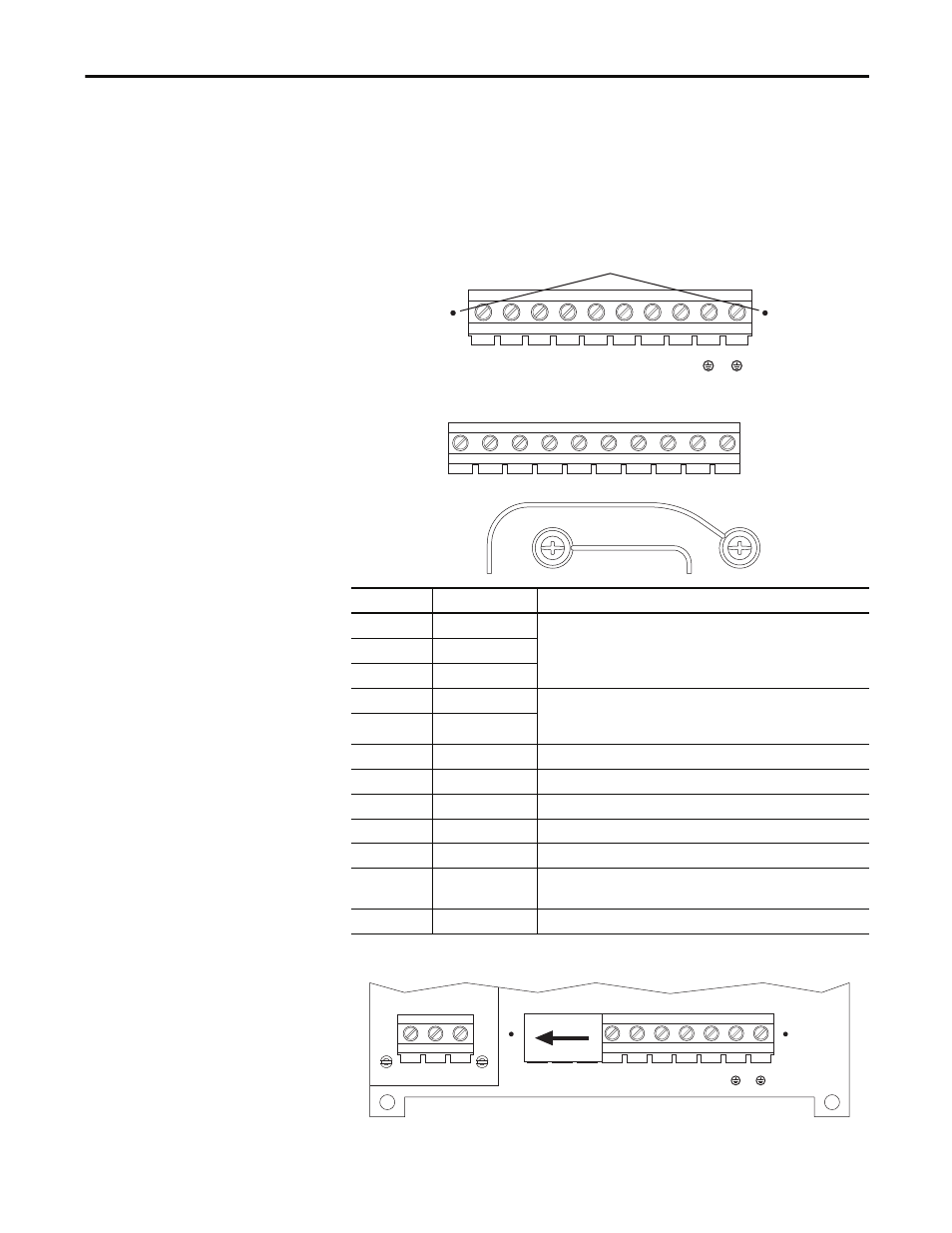
Cable Entry Plate Removal
If additional wiring access is needed, the cable entry plate on all drive frames can
be removed. Loosen the screws securing the plate to the heat sink and slide the
plate out.
Figure 8 - Frame A, B, C, D Power Terminal Block and DC Bus Test Points
Figure 9 - Frame E Power Terminal Block
Figure 10 - Power Input Terminals on Frame B with Internal RFI Filter Option
Terminal
Description
Notes
R
R (L1)
Three-phase AC line input power.
For single-phase input, connect to any two terminals.
S
S (L2)
T
T (L3)
BR1
DC brake
DB resistor connection - Important: Do not connect both an internal and
external DB resistor at the same time. This can violate the minimum
allowed DB resistance and cause damage to the drive.
BR2
DC brake
U
U (T1)
To the motor
V
V (T2)
To the motor
W
W (T3)
To the motor
PE
PE ground
–
PE
PE ground
–
-DC DC
bus
(–)
➊
Test point on Frames A, B, C, and D are to the left or right of the power
terminal block. Frame E has a dedicated terminal.
+DC DC
bus
(+)
–
L1
R
L2
S
L3
T
BR1
+DC
BR2
BRK
T1
U
T2
V
T3
W
PE PE
-DC
-DC
➊
L1
R
L2
S
L3
T
+DC –DC BR1 BR2
T1
U
T2
V
T3
W
PE
PE
M6
M6
L1
R
L2
S
L3
T
BR1
+DC
BR2
BRK
T1
U
T2
V
T3
W
PE PE
-DC
-DC
L1
R
L2
S
L3
T
- 20P PowerFlex DC Drive - Frame D Bimetal Thermostat (10 pages)
- 1336S_F_T_E_R F Frame Snubber Resistor Repl. (6 pages)
- 22-COMM PowerFlex 4-Class DSI (Drive Serial Interface) Network Communication Adapter (4 pages)
- 8-545 Plug In Solid State Relay (2 pages)
- 20-HIM-B1 PowerFlex 7-Class HIM Bezel (DPI) (4 pages)
- 100 Contactors with DC Coil (2 pages)
- 100 Contactors with DC Coil (1 page)
- 20P PowerFlex DC Drive - Frame D Switching Power Supply Circuit Board (6 pages)
- 140G-MTFx_MTHx_MTIx_MTKx Trip Unit Installation-140G-M (6 pages)
- 45BRD Analog Laser Sensor (4 pages)
- 20D Multi-Device Interface Option Board for PowerFlex 700S Drives (20 pages)
- 56RF RFID 18 mm Cylindrical Transceiver (2 pages)
- 42KC Miniature Rectangular: 5V DC Version (2 pages)
- 20P PowerFlex DC Drive - Frame A Switching Power Supply Circuit Board (16 pages)
- 21P-MISC-A-TP-2 Transition Tube Kit #C19-6/7 For PowerFlex 755 w/OEM Liquid Cooling Fr 6/7 Drive (2 pages)
- 42BT Background Suppression Sensor (3 pages)
- 42CB High Speed 18mm Cylindrical (4 pages)
- 140EX-JE2_JE3 Molded Case Circuit Breaker (4 pages)
- 140G-K-EAM1A Early Make Aux Contact for Rotary Handle Oper Mech-140G-K (1 page)
- 140G-K-EAM1A Early Make Aux Contact for Rotary Handle Oper Mech-140G-K (3 pages)
- 20-HIM-A6 PowerFlex (Human Interface Module) (74 pages)
- 42CF General Purpose 12mm Cylindrical (4 pages)
- 20D PowerFlex 700S Phase II Drive Frames 1...6 (80 pages)
- 140EX-HE1_HE2 Molded Case Circuit Breaker (6 pages)
- 140EX-HE1_HE2 Molded Case Circuit Breaker (4 pages)
- 20B PowerFlex 700 Custom Firmware - Pump Off (12 pages)
- 20-WIM-N4S DPI Wireless Interface Module (92 pages)
- 140U H-Frame Circuit Breaker Fixed and Adjustable Thermal Trip (2 pages)
- 140U H-Frame Circuit Breaker Fixed and Adjustable Thermal Trip (7 pages)
- 60-2619, 42JS Swivel/Tilt Mounting Bracket (1 page)
- 22A PowerFlex 4/40/400 Flange Mount (4 pages)
- 45MLA Controller Installation Instructions (16 pages)
- 20P PowerFlex DC Drive - Cooling Fan for Frame A Drives Above 73A at 230V 460V AC (6 pages)
- 42JS Series 7000 to 42JS VisiSight Replacement Kit (2 pages)
- 22A PowerFlex 4-Class HIM Bezel (DSI) (4 pages)
- 42CS Stainless Steel Photoelectric Sensors (4 pages)
- 20L-LL PowerFlex 700L Liquid-to-Liquid Heat Exchanger (40 pages)
- 20P PowerFlex DC Drive - Frame B SCR Modules (20 pages)
- 22B PowerFlex 40 Quick Start FRN 5.xx - 6.xx (161 pages)
- 22B PowerFlex 40 Quick Start FRN 5.xx - 6.xx (22 pages)
- 22F PowerFlex 4M Input RFI Filters (2 pages)
- 45LFM Capacitive Label Sensor (4 pages)
- 140G-Rx Installation Instruction-140G-R (2 pages)
- 140G-Rx Installation Instruction-140G-R (29 pages)
- 22C PowerFlex 400 AC Drive Quick Start - FRN 1-4.xx (28 pages)