Common symptoms and corrective actions, Common symptoms and corrective actions -8 – Rockwell Automation 20M LPM15 Liquid-Cooled Adjustable Frequency AC Drive FRN 2.xxx User Manual
Page 90
4-8
Troubleshooting
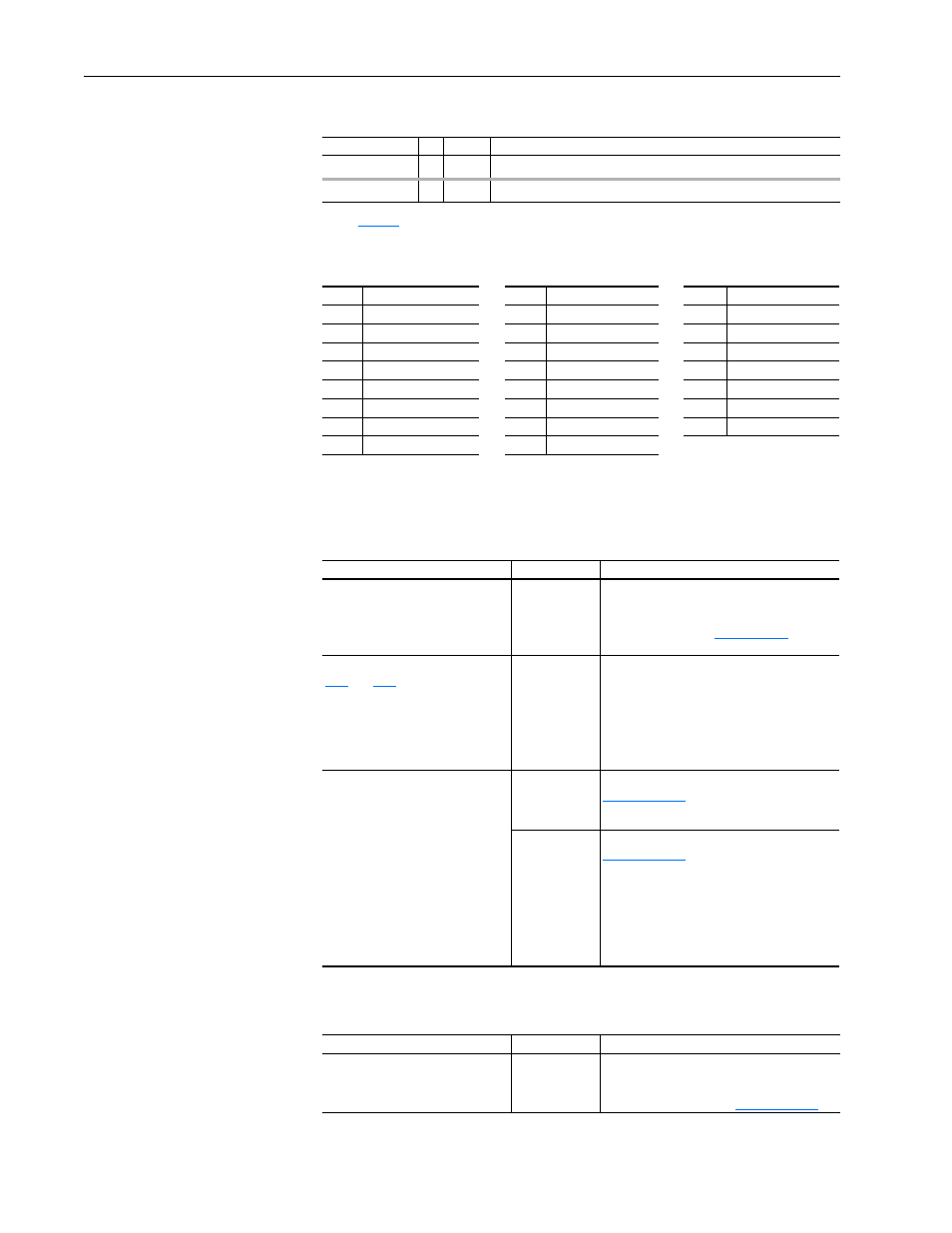
Table 4.D Alarm Cross Reference – by Number
Common Symptoms and
Corrective Actions
Drive does not Start from Start or Run Inputs wired to the terminal block.
Drive does not Start from HIM.
VHz Neg Slope
24
➁
[Torq Perf Mode] = “Custom V/Hz” & the V/Hz slope is negative.
Waking
11
➀
The Wake timer is counting toward a value that will start the drive.
(1)
for a description of alarm types.
No.
(1)
(1)
Alarm numbers not listed are reserved for future use.
Alarm
Alarm
No.
Alarm
1
Precharge Active
10
Decel Inhibt
23
MaxFreq Conflict
2
UnderVoltage
11
Waking
24
VHz Neg Slope
3
Power Loss
17
Dig In ConflictA
25
IR Volts Range
4
Start At PowerUp
18
Dig In ConflictB
26
FluxAmpsRef Rang
5
Analog in Loss
19
Dig In ConflictC
27
Speed Ref Cflct
6
IntDBRes OvrHeat
20
Bipolar Conflict
28
Ixo Vlt Rang
8
Drive OL Level 1
21
Motor Type Cflct
29
Sleep Config
9
Drive OL Level 2
22
NP Hz Conflict
Table 4.C Alarm Descriptions and Actions (Continued)
Alarm
No. Type
(1)
Description
Cause(s)
Indication
Corrective Action
Drive is faulted.
Flashing red
status light
Clear fault.
• Press Stop
• Cycle power
• Set [Fault Clear] to 1
• “Clear Faults” on the HIM Diagnostic menu.
Incorrect input wiring. See pages
for wiring examples.
• 2 wire control requires Run, Run
Forward, Run Reverse or Jog input.
• 3 wire control requires Start and Stop
inputs.
• Jumper from terminal 25 to 26 is
required.
None
Wire inputs correctly and/or install jumper.
Incorrect digital input programming.
• Mutually exclusive choices have
been made (i.e., Jog and Jog
Forward).
• 2 wire and 3 wire programming may
be conflicting.
• Exclusive functions (i.e, direction
control) may have multiple inputs
configured.
• Stop is factory default and is not
wired.
None
Program [Digital Inx Sel] for correct inputs.
Start or Run programming may be missing.
Flashing yellow
status light and
“DigIn CflctB”
indication on
LCD HIM.
[Drive Status 2]
shows type 2
alarm(s).
Program [Digital Inx Sel] to resolve conflicts.
Remove multiple selections for the same
function.
Install stop button to apply a signal at stop
terminal.
Cause(s)
Indication
Corrective Action
Drive is programmed for 2 wire
control. HIM Start button is disabled
for 2 wire control.
None
If 2 wire control is required, no action needed.
If 3 wire control is required, program [Digital
Inx Sel] for correct inputs.