Inputs & outputs file, Inputs & outputs file -28 – Rockwell Automation 20M LPM15 Liquid-Cooled Adjustable Frequency AC Drive FRN 2.xxx User Manual
Page 76
3-28
Programming and Parameters
Inputs & Outputs File
Fil
e
Gr
oup
No.
Parameter Name & Description
for symbol descriptions
Values
Related
INPUTS &
OUTPUTS
Analog In
put
s
320
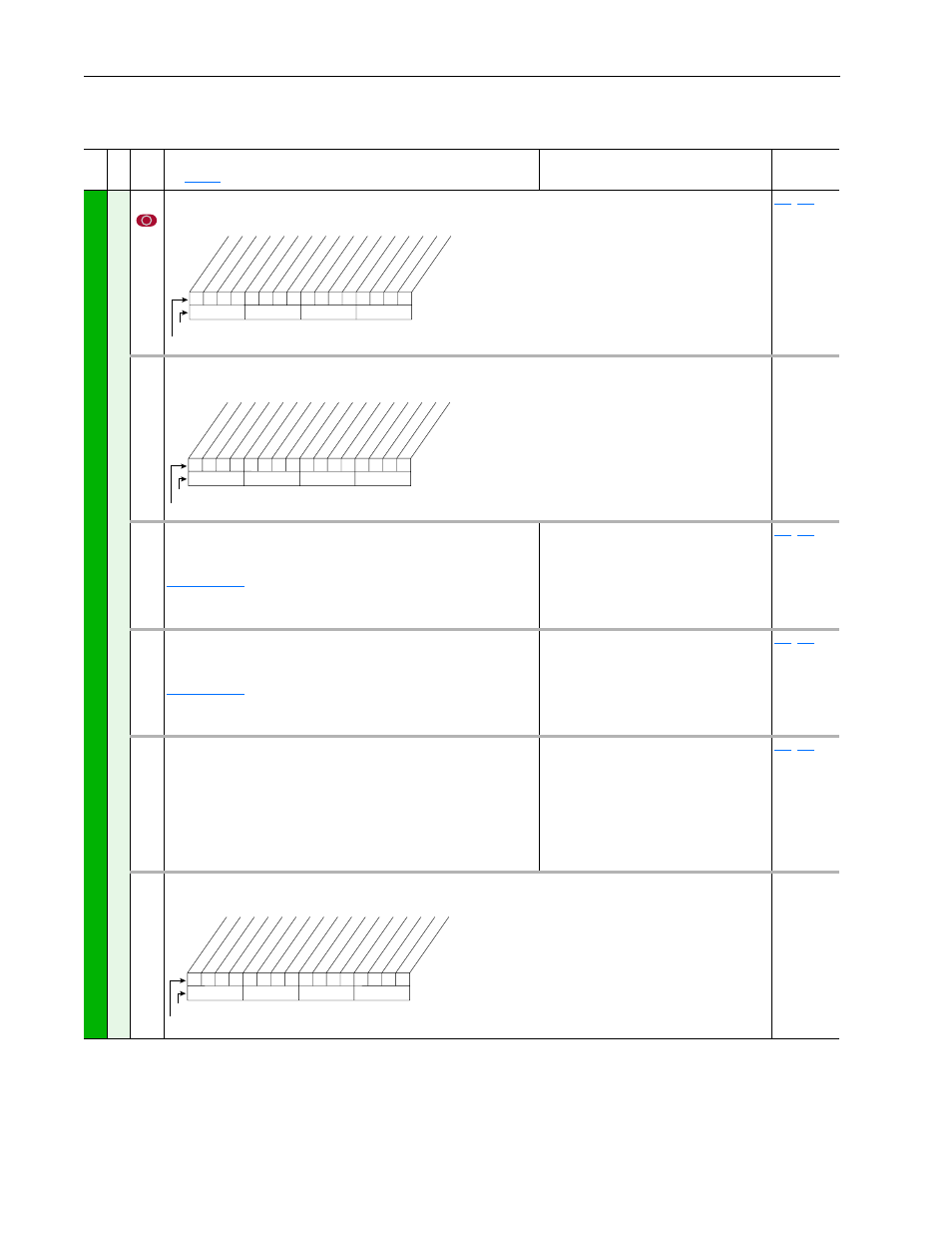
[Anlg In Config]
Selects the mode for the analog inputs.
,
321
[Anlg In Sqr Root]
Enables/disables the square root function for each input.
322
325
[Analog In 1 Hi]
[Analog In 2 Hi]
Sets the highest input value to the analog input x scaling block.
, parameter 320 defines if this input will be –/+10V or 4-20
mA.
Default:
Min/Max:
Units:
10.000 Volt
10.000 Volt
4.000/20.000mA
–/+10.000V
0.000/10.000V
0.001 mA
0.001 Volt
091
,
092
323
326
[Analog In 1 Lo]
[Analog In 2 Lo]
Sets the lowest input value to the analog input x scaling block.
, parameter 320 defines if this input will be –/+10V or 4-20
mA.
Default:
Min/Max:
Units:
0.000 Volt
0.000 Volt
4.000/20.000mA
–/+10.000V
0.000/10.000V
0.001 mA
0.001 Volt
091
,
092
324
327
[Analog In 1 Loss]
[Analog In 2 Loss]
Selects drive action when an analog signal loss is detected. Signal loss is
defined as an analog signal less than 1V or 2mA. The signal loss event
ends and normal operation resumes when the input signal level is greater
than or equal to 1.5V or 3mA.
Default:
Options:
0
0
0
1
2
3
4
5
6
“Disabled”
“Disabled”
“Disabled”
“Fault”
“Hold Input”
“Set Input Lo”
“Set Input Hi”
“Goto Preset1”
“Hold OutFreq”
091
,
092
340
[Anlg Out Config]
Selects the mode for the analog outputs.
0
x
x
0
x
x
x
x
x
x
x
x
x
x
x
x
10
0
1
2
3
4
5
6
7
8
9
11
12
13
14
15
1 =Current
0 =Voltage
x =Reserved
Bit #
Factory Default Bit Values
Analog In 1
Analog In 2
0
x
x
0
x
x
x
x
x
x
x
x
x
x
x
x
10
0
1
2
3
4
5
6
7
8
9
11
12
13
14
15
1 =Enable
0 =Disable
x =Reserved
Bit #
Factory Default Bit Values
Analog In 1
Analog In 2
x x
x
1
x
x
x
x
x
x
x
x
x
x
x
x
10
0
1
2
3
4
5
6
7
8
9
11
12
13
14
15
1 =Current
0 =Voltage
x =Reserved
Bit #
Factory Default Bit Values
Analog Out1