Rockwell Automation 20M LPM15 Liquid-Cooled Adjustable Frequency AC Drive FRN 2.xxx User Manual
Page 70
3-22
Programming and Parameters
UTILITY
Di
agnostic
s
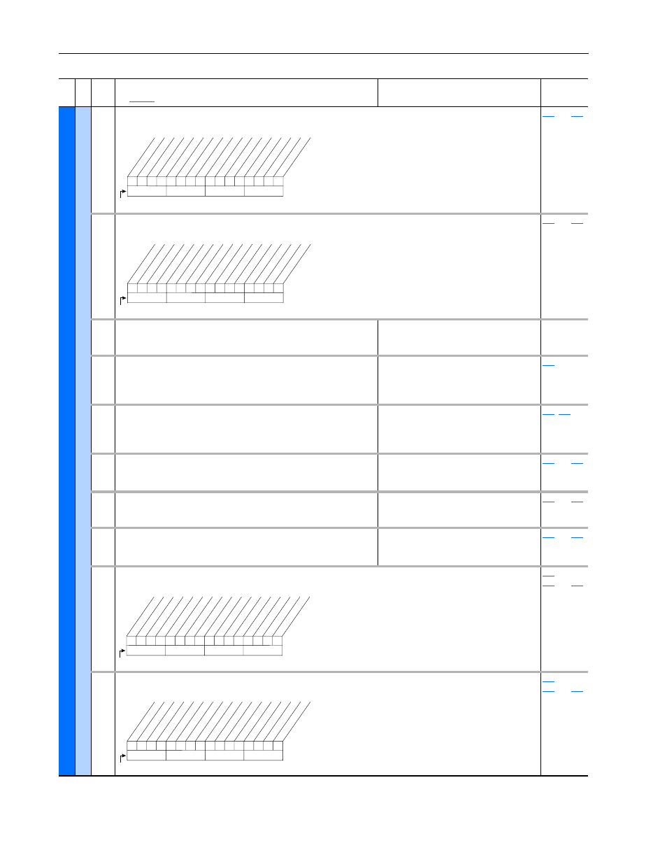
216
[Dig In Status]
Status of the digital inputs.
Read Only
thru
217
[Dig Out Status]
Status of the digital outputs.
Read Only
thru
218
[Drive Temp]
Present operating temperature of the drive power section.
Default:
Min/Max:
Units:
Read Only
0.0/100.0%
0.1%
219
[Drive OL Count]
Accumulated percentage of drive overload. Continuously operating the
drive over 100% of its rating will increase this value to 100% and cause a
drive fault or foldback depending on the setting of [Drive OL Mode].
Default:
Min/Max:
Units:
Read Only
0.0/100.0%
0.1%
220
[Motor OL Count]
Accumulated percentage of motor overload. Continuously operating the
motor over 100% of the motor overload setting will increase this value to
100% and cause a drive fault.
Default:
Min/Max:
Units:
Read Only
0.0/100.0%
0.1%
,
224
[Fault Frequency]
Captures and displays the output speed of the drive at the time of the last
fault.
Default:
Min/Max:
Units:
Read Only
0.0/+[Maximum Freq]
0.1 Hz
225
thru
230
225
[Fault Amps]
Captures and displays motor amps at the time of the last fault.
Default:
Min/Max:
Units:
Read Only
0.0/[Rated Amps]
× 2
0.1 Amps
224
thru
230
226
[Fault Bus Volts]
Captures and displays the DC bus voltage of the drive at the time of the
last fault.
Default:
Min/Max:
Units:
Read Only
0.0/Max Bus Volts
0.1 VDC
224
thru
230
227
[Status 1 @ Fault]
Captures and displays [Drive Status 1] bit pattern at the time of the last fault.
Read Only
209
,
224
thru
230
228
[Status 2 @ Fault]
Captures and displays [Drive Status 2] bit pattern at the time of the last fault.
Read Only
210
,
224
thru
230
Fil
e
Gr
oup
No.
Parameter Name & Description
See
page 3-2
for symbol descriptions
Values
Related
0
0
0
0
0
0
x
x
x
x
x
x
x
x
x
x
10
0
1
2
3
4
5
6
7
8
9
11
12
13
14
15
1 =Input Present
0 =Input Not Present
x =Reserved
Bit #
Digital In1
Digital In2
Digital In3
Digital In4
Digital In5
Digital In6
0
x x
0
x
x
x
x
x
x
x
x
x
x
x
x
10
0
1
2
3
4
5
6
7
8
9
11
12
13
14
15
1 =Output Energized
0 =Output De-energized
x =Reserved
Bit #
Digital Out1
Digital Out2
0
1
1
0
0
0
0
1
0
1
1
1
0
0
0
0
10
0
1
2
3
4
5
6
7
8
9
11
12
13
14
15
1 =Condition True
0 =Condition False
x =Reserved
Bit #
Read
y
Active
Command Dir
Actual Dir
Accelerating
Decelerating
Alarm
Faulted
At Speed
Local ID 0
Local ID 1
Local ID 2
Spd Ref ID 0
Spd Ref ID 1
Spd Ref ID 2
Spd Ref ID 3
0
0
0
0
0
0
0
x
0
0
0
0
0
0
x
x
10
0
1
2
3
4
5
6
7
8
9
11
12
13
14
15
1 =Condition True
0 =Condition False
x =Reserved
Bit #
Read
y
Active
Running
Jog
ging
Stopping
DC Braking
A
utoT
uning
A
utoRst Ctdn
A
utoRst Act
Curr Limit
Bus Freq Reg
Motor Overld
DPI at 500 k