Communication file, Communication file -25 – Rockwell Automation 20M LPM15 Liquid-Cooled Adjustable Frequency AC Drive FRN 2.xxx User Manual
Page 73
Programming and Parameters
3-25
Communication File
Fil
e
Gr
oup
No.
Parameter Name & Description
for symbol descriptions
Values
Related
COMMUNIC
A
TION
Comm Contr
o
l
270
[DPI Data Rate]
Sets the baud rate for attached drive peripherals. When changing this
value the drive must be reset for the change to take affect.
Default:
Options:
1
0
1
“500 kbps”
“125 kbps”
“500 kbps”
271
[Drive Logic Rslt]
The final logic command resulting from the combination of all DPI and discrete
inputs. This parameter has the same structure as the product-specific logic
command received via DPI and is used in peer-to-peer communications.
Read Only
272
[Drive Ref Rslt]
Present frequency reference scaled as a DPI reference for peer-to-peer
communications. The value shown is the value prior to the accel/decel
ramp and the corrections supplied by slip comp, PI, etc.
Default:
Min/Max:
Units:
Read Only
–/+32767
1
273
[Drive Ramp Rslt]
Present frequency reference scaled as a DPI reference for peer-to-peer
communications. The value shown is the value after the accel/decel ramp,
but prior to any corrections supplied by slip comp, PI, etc.
Default:
Min/Max:
Units:
Read Only
–/+32767
1
Mas
ks & Owne
rs
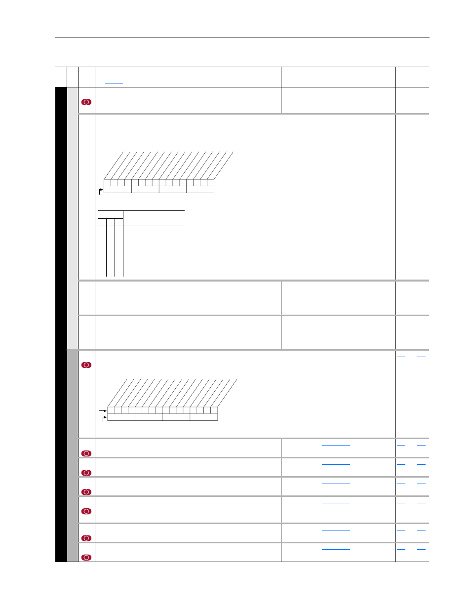
276
[Logic Mask]
Determines which adapters can control the drive. If the bit for an adapter is set to “0,” the adapter will have no control
functions except for stop.
thru
277
[Start Mask]
Controls which adapters can issue start commands.
See
thru
278
[Jog Mask]
Controls which adapters can issue jog commands.
See
thru
279
[Direction Mask]
Controls which adapters can issue forward/reverse direction commands.
See
thru
280
[Reference Mask]
Controls which adapters can select an alternate reference; [Speed Ref A,
B Sel] or [Preset Speed 1-7].
See
thru
281
[Accel Mask]
Controls which adapters can select [Accel Time 1, 2].
See
thru
282
[Decel Mask]
Controls which adapters can select [Decel Time 1, 2].
See
thru
0
1
1
0
0
0
0
1
0
1
1
1
0
0
0
0
10
0
1
2
3
4
5
6
7
8
9
11
12
13
14
15
1 =Condition True
0 =Condition False
x =Reserved
Bit #
Stop
Star
t
Jog
Clear F
ault
Forwar
d
Re
ver
se
Local Contrl
Mop Inc
Accel 1
Accel 2
Decel 1
Decel 2
Spd Ref ID 0
(1)
Spd Ref ID 1
(1)
Spd Ref ID 2
(1)
MOP Dec
Bits
(1)
Description
14 13 12
0
0
0
0
1
1
1
1
0
0
1
1
0
0
1
1
0
1
0
1
0
1
0
1
No Command - Man. Mode
Ref A Auto
Ref B Auto
Preset 3 Auto
Preset 4 Auto
Preset 5 Auto
Preset 6 Auto
Preset 7 Auto
1
1
1
1
1
1
x
x
x
x
x
x
x
x
x
x
10
0
1
2
3
4
5
6
7
8
9
11
12
13
14
15
1 =Control Permitted
0 =Control Masked
x =Reserved
Bit #
Factory Default Bit Values
Digital In
DPI P
or
t 1
DPI P
or
t 2
DPI P
or
t 3
DPI P
or
t 4
DPI P
or
t 5