Rockwell Automation 20M LPM15 Liquid-Cooled Adjustable Frequency AC Drive FRN 2.xxx User Manual
Page 130
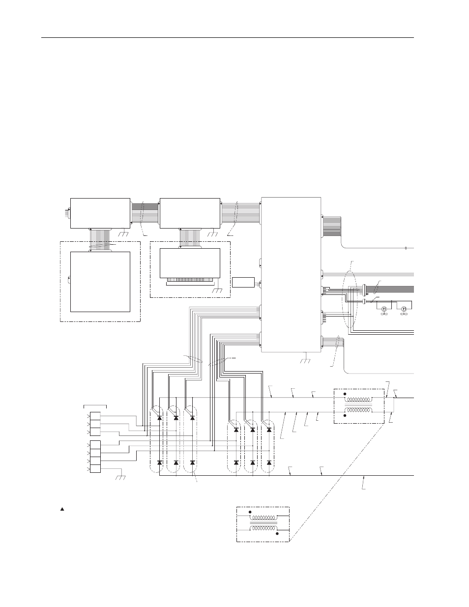
F-2
C-Frame LPM15 Drive Wiring Diagram
180508-Q01
20
AC Power
Input Leads
GND
L4
179026
L6
L5
179024
179022
L3
L2
179022
179023
L1
179025
L1N
L2N
L1P
L2P
22501-025-04
6 Places
SCR6
L6P
L3N
L6N
L3P
L4N
L5N
L5P
SCR5
L4P
SCR4
(12-Pulse Configuration)
Reactor
50 uh
2
3
1
179000
4
179012
Laminated Bus Assy
(6-Pulse Configuration)
179027
179034
179036
179035
179031
179038
1
REACTOR
50 uh
2
179039
J2
J3
INVERTER CONTROL
179784
SCR2
SCR1
BOARD OPTION(S)
J1
RIO
DeviceNet
TB1
COMMUNICATIONS INTERFACE
J2
J5
179726
J1
J7
J2
CONTROL ASSEMBLY
180493-A02 - 450HP
180493-A03 - 600HP
SCR3
179785
J5
See DETAIL A for
User Connections
STANDARD I/O OPTION(S)
J2
SCR Gate-
Cathode
S1, S2, S3
SCR Gate-
Cathode
S4, S5, S6
J9
AC Lline Sync
179037
179035
179031
179786
3
Current
Feedback
Gate Kill
179000
4
179040
179033
J10
DC Bus/
Cap Bank
Mid-Point
Temp. Sw./
Fan Power
25 KHz PS
J4
J3
179788
J6
P1
POWER INTERFACE
180505-A01
J1
J11
Main Control
Interface
Gate Driver
Interface
J7
J1
ControlNet-Coax
ControlNet-Fiber
RS485, DF-1
RS485, HVAC
PROFIBUS DPV1
EtherNet/IP
Interbus
LonWorks
N/A
OPTIONAL
24V DC - 180524-A01
120V AC - 180525-A01
NO I/O
179864-Q02
179865-Q02
194706-Q02
OPTIONAL
Jumper
180497-Q01
COMMUNICATION
Fan
179196
Fan
179196
P3 P4
180527-Q01
P2
NOTES:
1.) Symbol designates PIN 1 location of connectors.
2.) For S6 hookup: L1 is connected to L4.
L2 is connected to L5.
L3 is connected to L6.
3.) For S12 hookup: AC power is attached individually to L1 thru L6.