14 installation/wiring – Rockwell Automation 22F PowerFlex 4M User Manual FRN 1.xx - 2.xx User Manual
Page 24
1-14
Installation/Wiring
PowerFlex 4M Adjustable Frequency Drive FRN 1.xx - 2.xx User Manual
Publication 22F-UM001D-EN-E
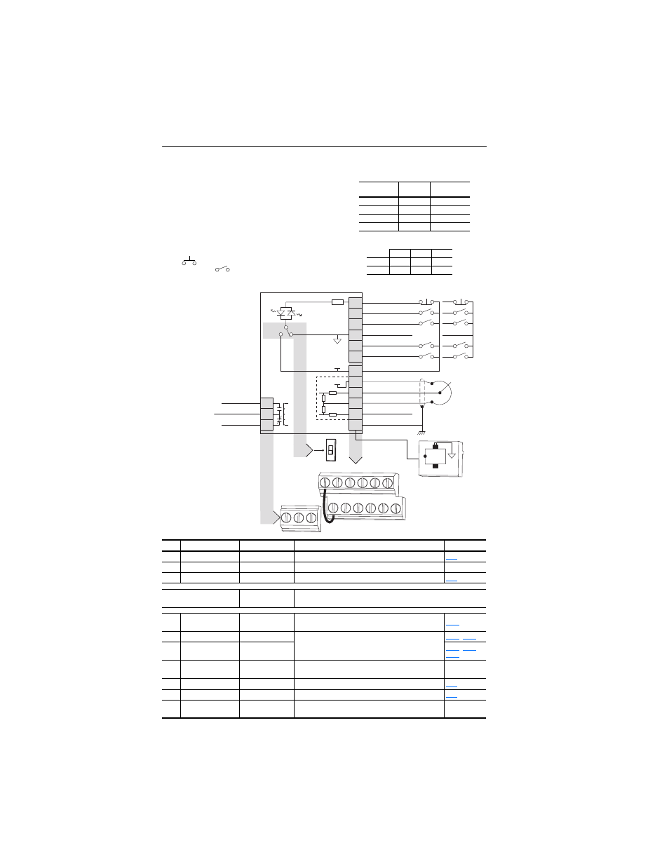
Figure 1.5 Control Wiring Block Diagram
No.
Signal
Default
Description
Param.
R1
Relay N.O.
Fault
Normally open contact for output relay.
R2
Relay Common
–
Common for output relay.
R3
Relay N.C.
Fault
Normally closed contact for output relay.
Sink/Source DIP Switch
Source (SRC)
Inputs can be wired as Sink (SNK) or Source (SRC) via DIP Switch
setting.
01
Stop
(1)
Coast
The factory installed jumper or a normally closed input
must be present for the drive to start.
(1)
02
Start/Run FWD
Not Active
Command comes from the integral keypad by default. To
disable reverse operation, see A095 [Reverse Disable].
,
03
Direction/Run REV
Not Active
,
,
04
Digital Common
–
For digital inputs. Electronically isolated with digital inputs
from analog I/O.
05
Digital Input 1
Preset Freq
Program with t201 [Digital In1 Sel].
06
Digital Input 2
Preset Freq
Program with t202 [Digital In2 Sel].
11
+24V DC
–
Drive supplied power for digital inputs.
Maximum output current is 100mA.
01
02
03
04
05
06
11
12
13
14
15
16
Stop
(1)
Start/Run FWD
(2)
Direction/Run REV
Digital Common
Digital Input 1
Digital Input 2
R1
R2
R3
Relay N.O.
Relay Common
Relay N.C.
+24V DC
+10V DC
0-10V In
Analog Common
4-20mA In
RS485 Shield
+24V
+10V
SRC
SNK
Typical
SNK Wiring
Typical
SRC Wiring
R1 R2 R3
1
8
RS485
(DSI)
SNK
SRC
01
02
03
04
05
06
11
12
13
14
15
16
(1)
Potentiometer
must be
1-10k ohm
2 Watt Min.
30V DC 125V AC 240V AC
Resistive
3.0A
3.0A
3.0A
Inductive
0.5A
0.5A
0.5A
(1)
Important: I/O Terminal 01 is always a coast to stop input except
when P106 [Start Source] is set to “3-Wire” control. In three wire
control, I/O Terminal 01 is controlled by P107 [Stop Mode]. All other
stop sources are controlled by P107 [Stop Mode].
Important: The drive is shipped with a jumper installed between I/O
Terminals 01 and 11. Remove this jumper when using I/O Terminal
01 as a stop or enable input.
(2)
Two wire control shown. For three wire control use a momentary
input
on I/O Terminal 02 to command a start. Use a
maintained input
for I/O Terminal 03 to change direction.
P106
[Start Source]
Stop
I/O Terminal 01
Stop
Keypad
Per P107
Coast
3-Wire
Per P107
Per P107
2-Wire
Per P107
Coast
RS485 Port
Per P107
Coast